MAS Observatory

|
|
This section remains as it was when I wrote it in 2003. The technology has changed a bit over the years but the goals of remote imaging are the same. This section contains a somewhat detailed account of the construction of my first observatory, the MAS (Maine Astronomical Society) Observatory. This observatory was 14 x 17 feet with a roll-off roof design. The observatory itself is fully robotic and can be run, from opening the roof, to imaging and processing, via remote desktop. It utilizes a number of SmartHome devices, including a SmartHome USB interface. Much of the credit for this successful design goes to John Smith, who was instrumental in his capacity as my consultant. Both he, and Ron Wodowski (through his book) were instrumental in guiding me to a solid mount and quality telescope. I hope these pages are helpful to others who are attempting a project such as this.
This observatory was closed down when I moved back to California in October of 2006
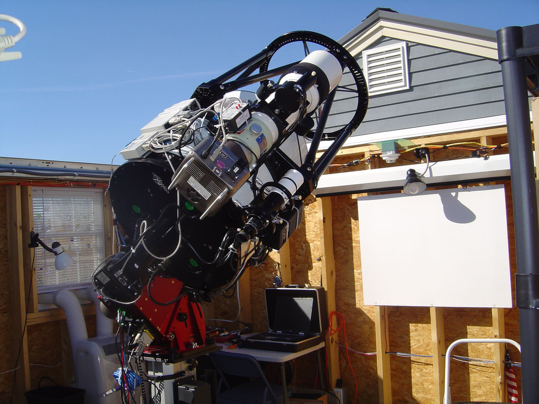
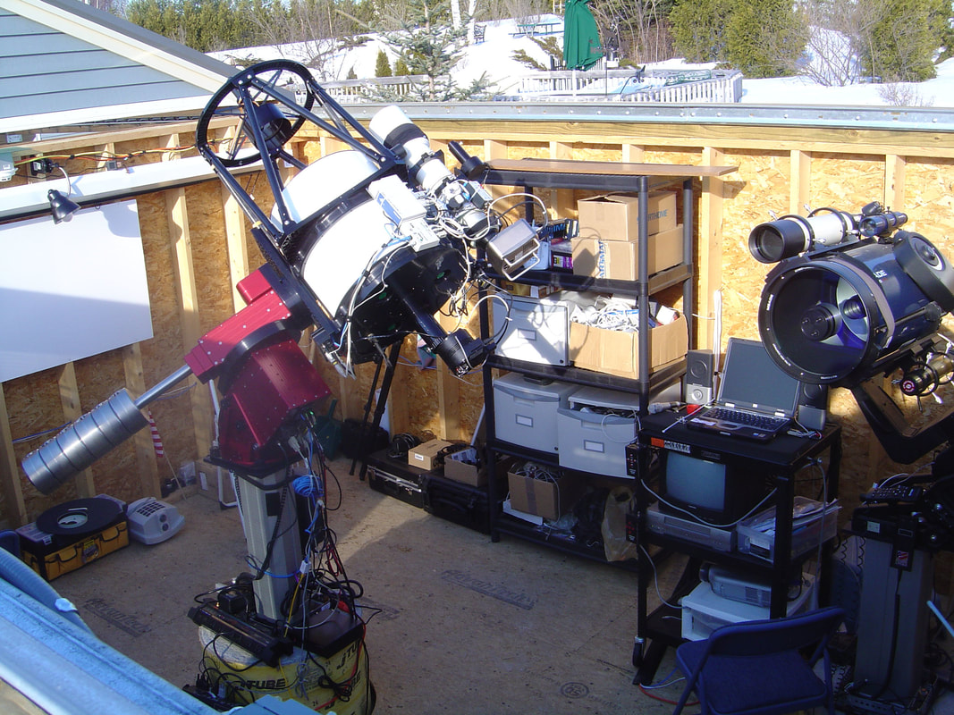
OVERVIEW: This area summarizes the construction of my second observatory (the first is shown below, and is no longer in use). This observatory has the ability to operate either remotely or locally, and has two main telescopes (each with a piggyback 4" refractor). The main telescope is an RC Optical 16" Ritchey-Chetien Reflector (primarily for photographic use) and the secondary telescope is a 12" GPS LX-200 (primarily for video/visual use at star parties). Although owned and built at my personal time and expense, the observatory is available on a limited basis interested groups and to the Maine Astronomical Society, primarily during star parties. The site is being updated frequently so that those who are interested in building an observatory can follow along with the trial and tribulations of this project. Again, I have been very fortunate to have John Smith ( www.hiddenloft.com ) as my consultant on this project.
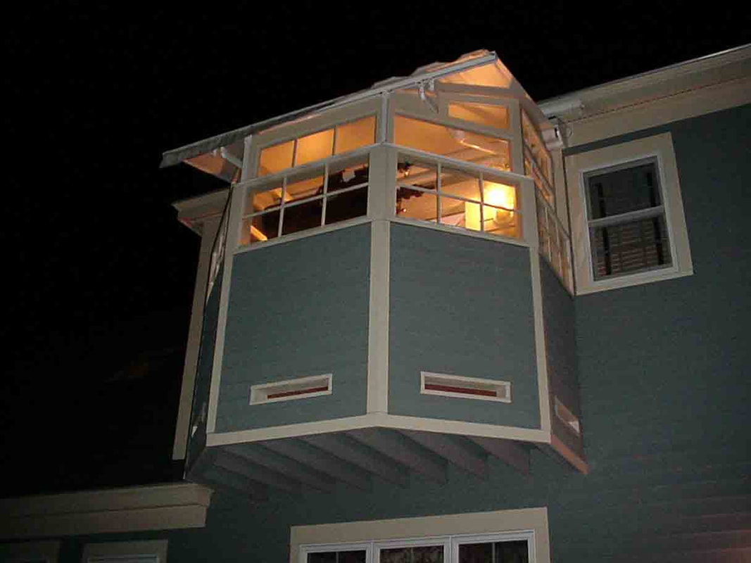
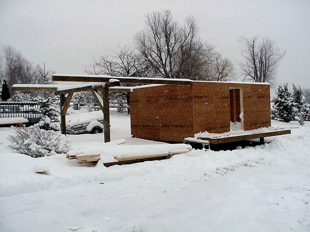
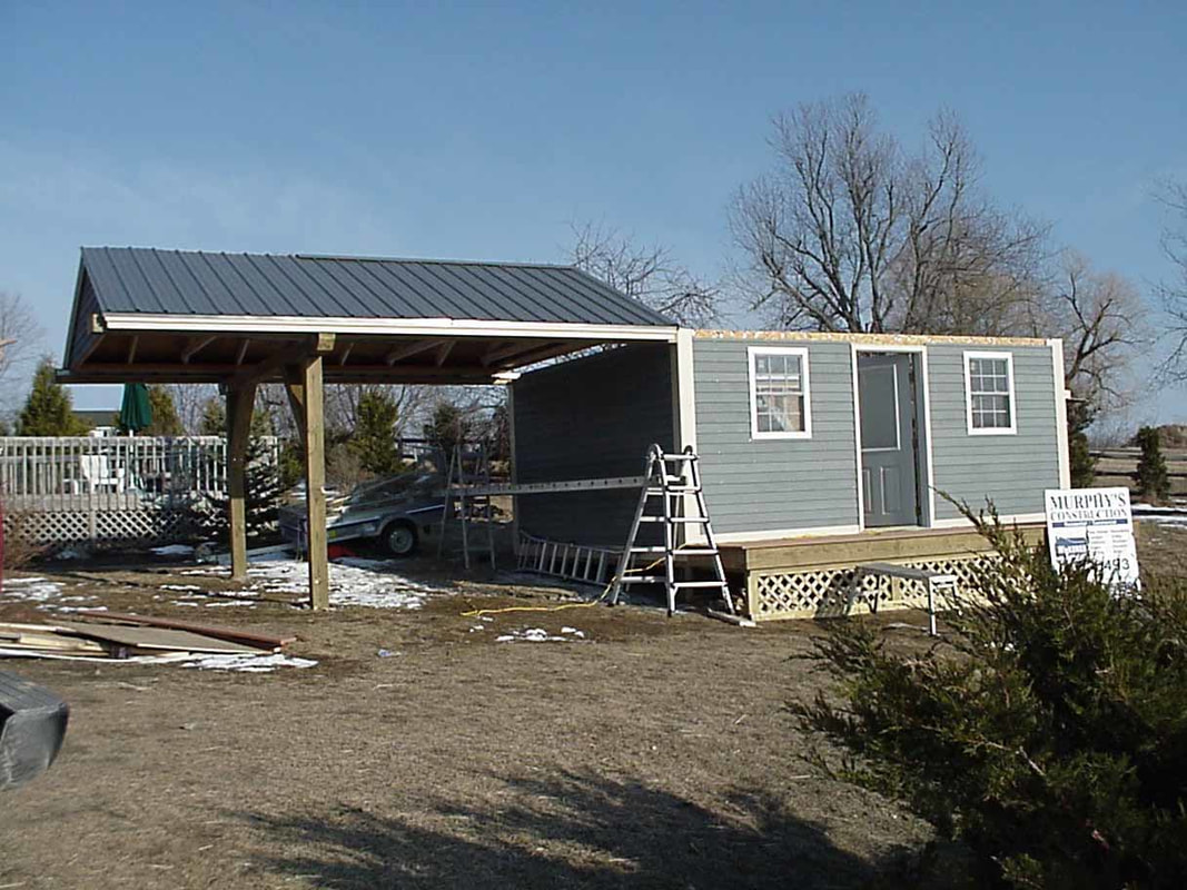
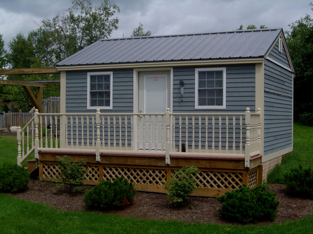
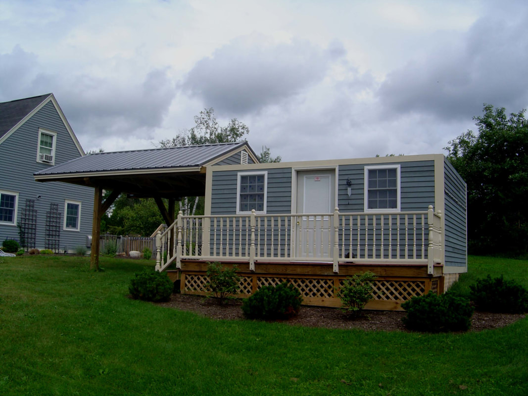
The original site was put together with great thought and care and, sadly, with nearly every "observatory" mistake possible. The observatory was methodically and strongly built with millimeter tolerances, by an extremely talented carpenter (Paul Murphy of Murphy's Construction, in Lewiston, Maine). The windows hinge open and the roof opens with the push of a button. It seemed pefect for our cold weather, snow and storms. Unfortunately, the site overlooks a heat absorbing flagstone patio and heated pool, causing poor seeing at night from the continued release of heat and moisture. As can be seen, no pier was dropped to the ground. Instead, the scope is on a heavy duty tripod (with vibration suppression pads) on a deck (well built, but still guaranteed to move and migrate with temperature, causeing alignment and guiding problems). It was intentionally built on the side of our house for winter convenience and to block the wind. Unfortunately, this location also blocked all west views and has a door right next to the scope, adding to heat problems every time the door was opened. Did I do anything right? Perhaps it remains a nice way to quickly view through the scope during a Maine winter, but it was a nightmare for autoguiding long exposures.
|
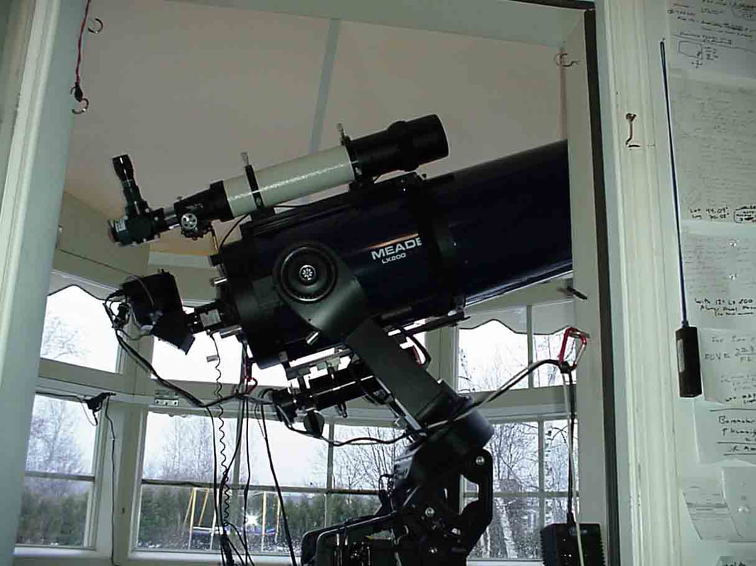
So much for the original site. As to the equipment in the original site, things were not much better. The workhorse had been the well known Meade 12" GPS LX-200. You'll be seeing that the new observatory is being built around an RC Optical Ritchey-Chretien Reflector with a Paramount ME mount. The Meade 12" GPS LX-200 will remain a part of this observatory (primarily for star party visual/video use). My own personal experience is that these telescopes are excellent for observing and video astrophotoraphy and my Meade telescopes introduced me to the world of amateur astronomy. As to the accuracy of its' autoguiding abilities at its' 3000 mm focal length, much has been written, and I'll leave others to draw their own conclusions. Some have succeeded in using this platform for deep sky imaging with the use of adaptive optics (which can, to some extent, compensate for RA periodic errors and RA/Dec random errors). With the use of focal length reducers and adaptive optics, I was able to use this system for deep sky astrophotography. At longer (3000 mm) focal lengths, I have been less successful with my Meade telescope, possibly due to my own lack of skill. For long focal length exposures many recommend a "more solid" (and, of course, much more expensive ) mount, such as Software Bisque's Paramount ME, or an Astro-Physics mount. Obviously I chose this option, as my major interest is deep sky imaging. However, for my own part, I will continue to enjoy my LX-200 and have kept a 12" GPS LX-200 in my observatory. I find it to be a marvelous instrument for introducing others to amateur astronomy and for video astrophotography (also, Meade has a new deep sky imaging system which, by all reports, works well and is relatively inexpensive). As will be seen, for this observatory the main imaging system (which can be robotically controlled) utilizes an RCOS-16 Reflecor (for long focal length deep sky imaging) on a Paramount ME mount. A Takahashi 106 FSQ will be piggybacked to the RC for wide field astrophotography. The imaging cameras will be an SBIG STL-6303 for the RC-16 and an SBIG STL-11000 for the Takahashi 106 FSQ. You will see a brief mention of experimenting with an SBIG AO system (with the Paramount ME, I am unsure as to how much difernce the adaptive optics will make). The Meade scope is attached to an Astrovid StellaCam EX (with a Meade 3.3 FLR) for deep sky live video imaging at star parties. An invaluable resource for anyone thinking about a scope, mount, observatory or (and especially) CCD imaging is Ron Wodaski's "The New CCD Astronomy" ( www.wodaski.com ). Get it and read it twice, if I had, I wouldn't be buiding a 'second' observatory !!!
|
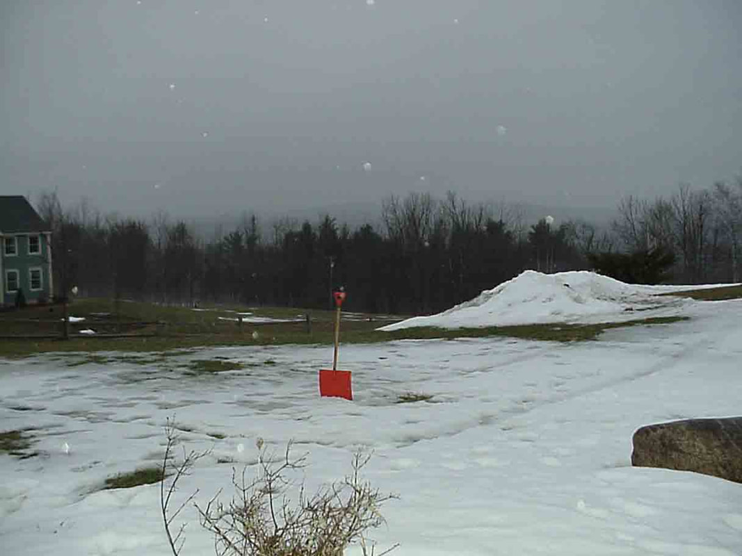
I agree, there may not seem to be much to see yet (the shovel marks the spot). However, a closer look and a lttle imagination can change this. The new site is to the south of our home, with essentially unobstructed views (even the pole star is easily seem to the north). There will be two 5' deep concrete/reinforced foundations and Pier-Tech adjustible piers ( www.pier-tech.com ), all completely isolated from the observatory (to decrease alignment and vibration problems). By the way, check out Pier-Tech's remote observatory, its an engineering marvel, comes as a kit, is made of anodized aluminum (maintence free) and has self-retracting rails. Its a great option for slightly smaller observatories where you don't need to match the "look" of the observatory to your home (these were two major requirements of our observatory, hence we went with the Sky Shed design). Our structure will be a 14 x 17 foot robotically controlled roll-off roof observatory, built with the award winning designs (roll off roof with the "look" of a shed) developed by SkyShed (www.skyshed.com , more on the Sky Shed design later). With most viewing directions there are no significant night-time heat sources. As with any setup there are always compromises. We do have neighbors and there will be some light polution. Most of this can be blocked, and on those very rare nights of exceptional seeing, they will dim their lights for us. Yes, after storms I will need to blaze a trail to the structure. But since the structure will be robotically controlled, I will rarely 'need' to go there. Rather I can go out when I want to, to change lenses, to look through them, or for star parties. And yes, there will be some wind from the west (Mt Washington), but the scope will be lowered for autoguiding (protecting it from the wind) and can be raised for viewing (thanks to the Pier-Tech). Again, many thanks to John Smith for his engineering and astronomical skills in consulting on this project ( www.hiddenloft.com ). His site is filled with useful information and is highly recommended. The main telescope will be an RC Optics 16" Ritchey-Cretien Truss telescope ( www.rcopticalsystems.com) with a piggyback Takahashi FSQ 106, placed on a Software Bisque Paramount ME mount (www.bisque.com). The secondary scope will be a 12" GPS LX200 with piggyback wide view 4" TeleVue; both primarily for visual and video use. These will be secured to the adjustible Pier-Tech piers and will be placed under the roll-off-roof observatory. Imaging (primarily with the 16" RC) will be through an SBIG ST10-XME with adaptive optics, SBIG STV (www.sbig.com) and Meade USB Autostar Suite Lunar/Planetary Camera (www.meade.com). Updates to this site will be added periodically as the construction moves along.
|
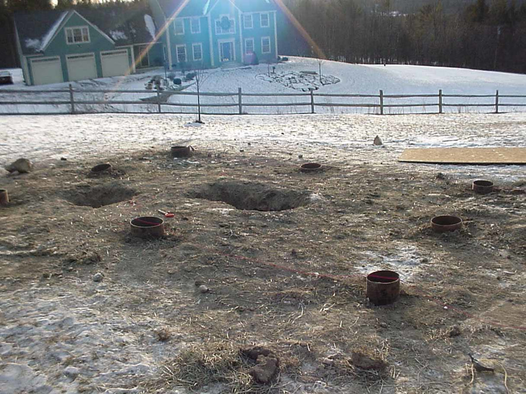
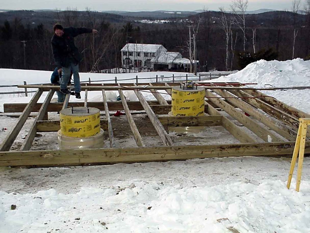
After multiple discussions with John Smith (consultant) and Wayne and Brad at Sky-Shed, we decided on a 12 x 16 foot structure with the two teslescopes as noted previously. Using the "bigger is better" principle, the shed size was increased to 14 x 17 foot. The conditions were, and are at the time of tnis writing, sub-zero, with a 2 foot frost wall which was machined through (Murphy's Construction). The two 5 foot piers holes can be seen as well as several 4 foot deep sonotubes for the posts on which the deck, and therefore the Sky-Shed, will be built. We chose this design because of the fierce winter conditions, in order to decrease any shifting of the Sky-Shed (usually it is built on the ground and works quite well, even in the northeast).
|

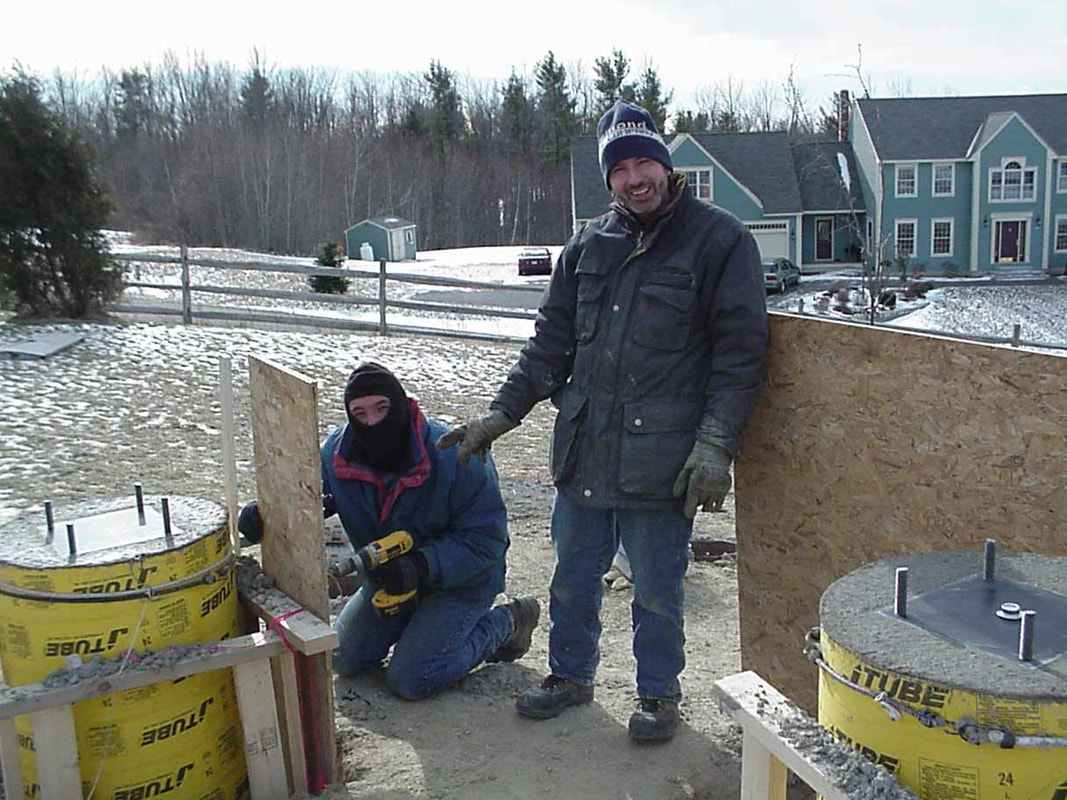
Here I am, standing in the 5 foot deep (5 ft x 4 ft x 2 ft) hole in which the rebar and concrete will be poured (I plan to get out first). The RC16 telescope will sit on 40 cubic feet of concrete, hopefully more than enough to hold it absolutely steady. The depth is critical so as to ensure we are below the frost layer. The hole will be poured with forms in place to decrease any shifting of the cement which could occur during the winter. Over the next few days the concrete will be poured. The base plate, on which the Paramount ME will be mounted, will be aligned to true north (using the shadow of the sun as it transits the meridian) and leveled using a nicely machined Software Bisque leveler.
|
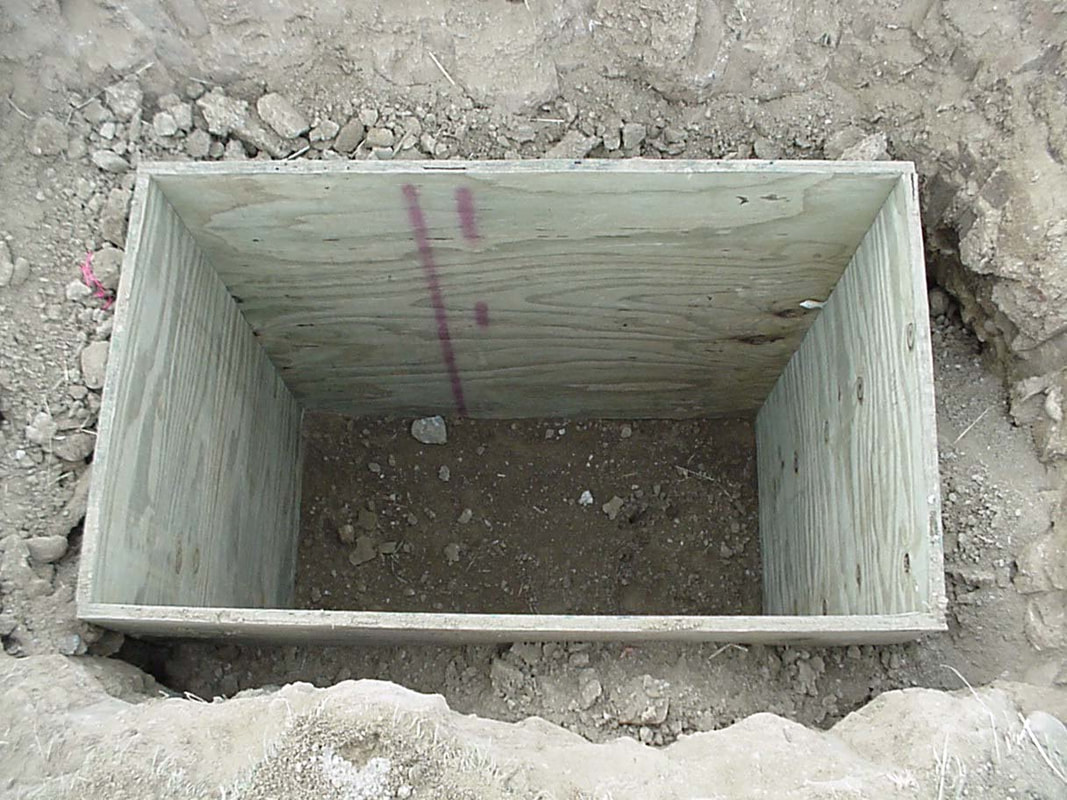
The forms were put together today (1/22/04). This form is about 4 x 3 feet with a depth of 5 feet. Tomorrow the rebar will be placed and true north will be determined using the sun as it passes the meridian. This will ultimately hold the RC-16 telescope with the piggy back 4 inch Takahashi refractor. The form for the GPS LX200 is 2 x 2 feet and also 5 feet deep.
|
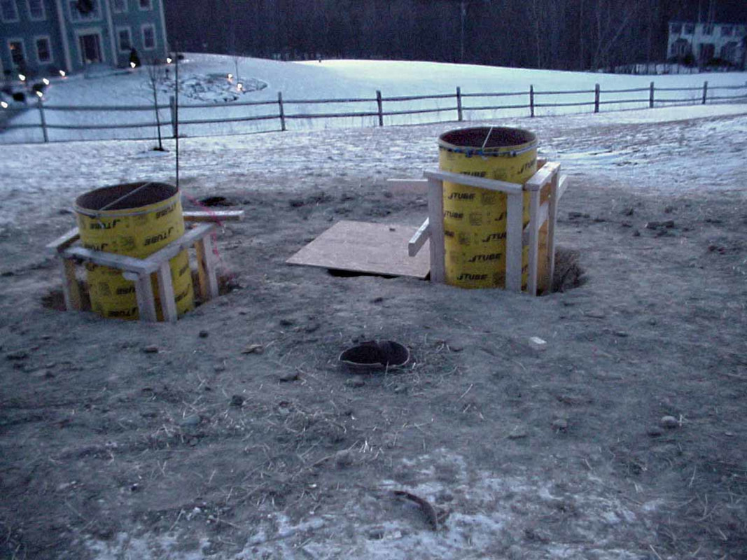
The Sonotubes are in place above the forms. I've set their base one foot below the surface, right ar the highest point of the underlying foundation. This way, if we should move, we could take the entire observatory, knock out the piers and cover the rest with earth. The sonotubes appear high because the observatory will be built on a deck. The RC-16 pier will be 18 inches above the 'floor', with the LX-200 12 inches above the 'floor'.
|
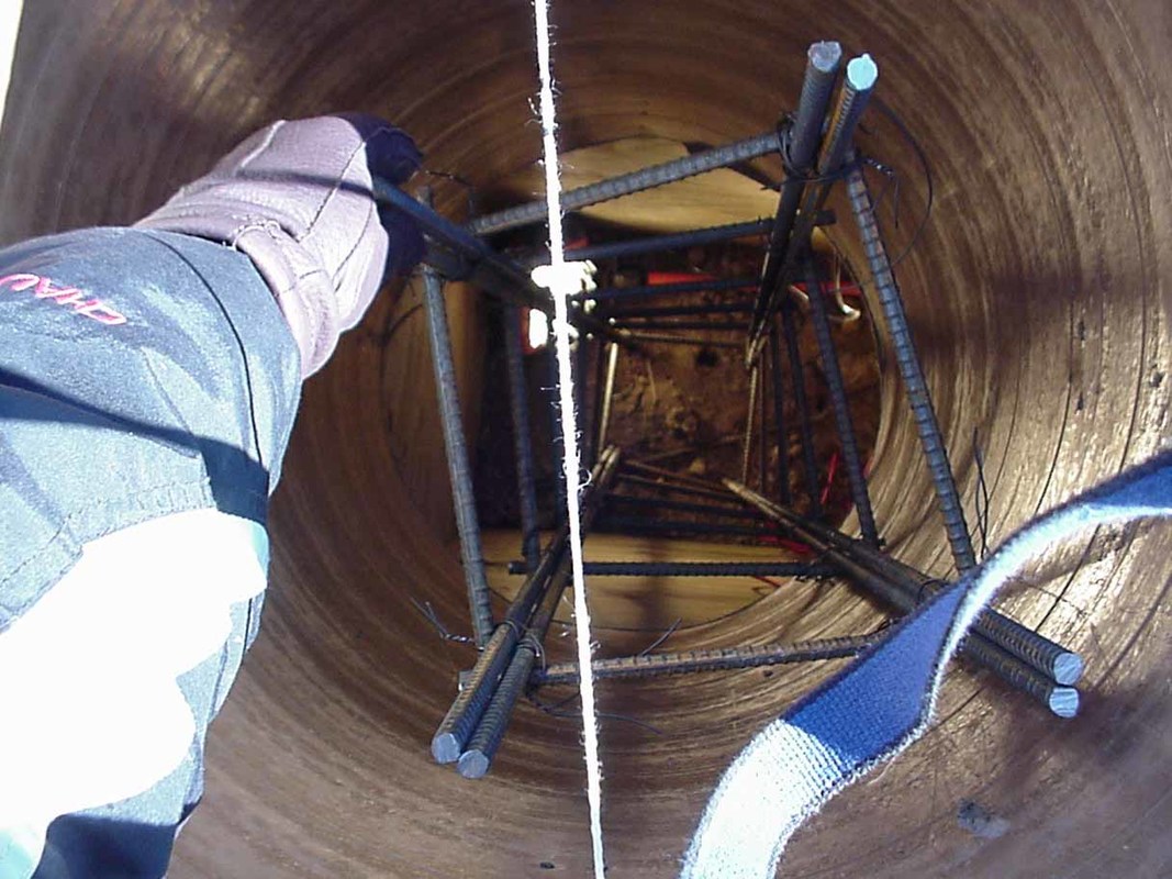
The rebar has been placed within the foundation base (down to 5 feet) and within the sonotube. Rebar is also pounded into the ground at the base of the foundation. Before pouring the concrete the north/south direction will be determined a third time (I've done it twice so far) using the sun transit system. Two simple variations of this techinique will be shown in a future photograph. This work was done with the temperature at -5 deg F with a wind chill factor of -30 degrees (hense the need for a robotic/remote observatory during the winter).
|
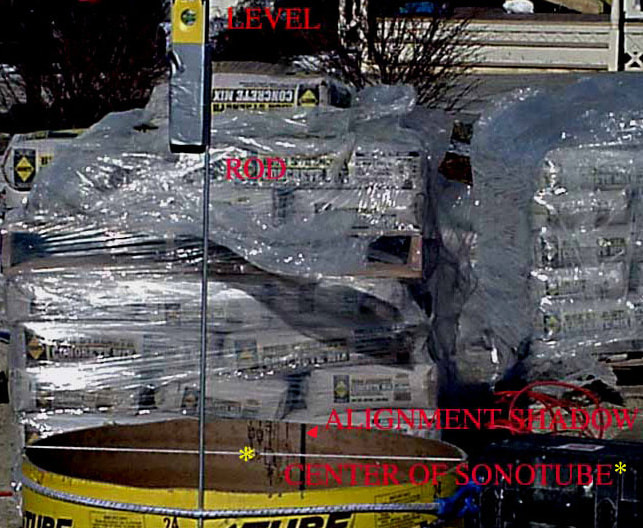
True north was determined by using the shadow cast by a perpendicular rod as the sun transit occured (as the sun passes from east to west). This time was determined by "The Sky" and "Starry Nignt" for my latitude and longitude (11:52 AM). The exact time was determined by setting my watch using "nistime-32bit" (can obtain off net). There were 20 mph gusts (-30 F wind chill), making a plumb bob impractical. Therefore a level was placed on the rod and the exact center of the sonotube was carefully marked on a string. The shadow must pass through the center of the sonotube and the rod must be perpendicular (hence the level). I marked the shadow (and exact location of the rod) for 11:30, 11:40, 11:52 (transit), 12:00 and 12:10 (Download and magnify photo for details; asterix marks center of sonotube along the string).
|
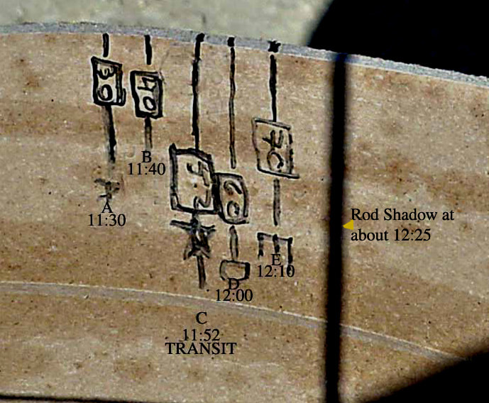
As can be seen, the shadow of the sun on the opposite side of the sonotube(cast by a vertical line, ie, the rod; and directed through the center of the sonotube) was taken at several intervals before, during and after the sun's transit. The spacing between these points (taken at 11:30, 11:40, 11:52((transit)), 12:00 and 12:10) is essentially as would be expected (noting that the transit point is 12 minutes after the 12:40 mark). These extra points are advisable, in case some error is made at the transit point.
|
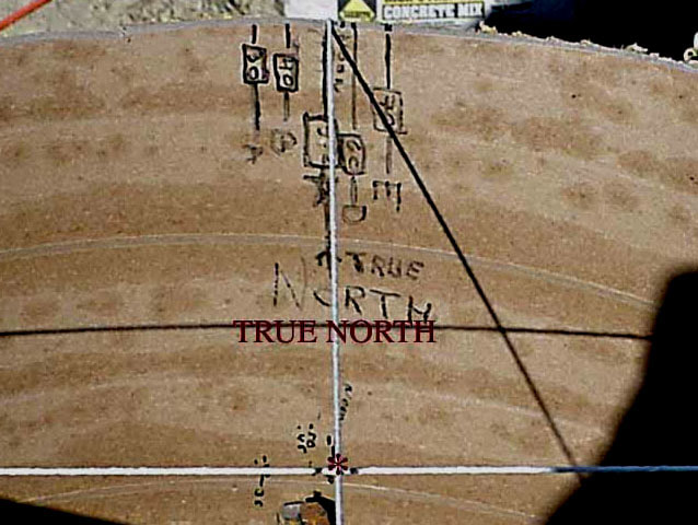
The direction of true north follows a line from the point at which the rod contacted the sonotube, extending through the center of the sonotube (marked here with an asterix), and ending where the shadow contacted the opposite side of the sonotube. These points will be securely marked with two nails in the sonotube with a string running between them. The mounting plate has also been scribed (using a T-square) through its center and these two lines will be aligned. Please note that in determining north its best to have the surface of the sonotube level, so that the center of the sonotube can be easily measured, and to ensure multiple points (before and after transit) will be be evenly separated when comparing points before and after transit.
|
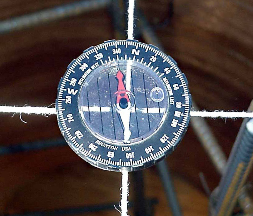
John Smith warned me about using a compass (he's known of a few disasters trying to set north with a compass). The transit method is combersome and it is very tempting to use a compass (manual or electronic). This diagram shows how inaccurate this can be. This compass it the standard Meade LX200 compass which has been adjusted for magnetic north (and confirmed with a LX-200 which is exactly polar alligned). As can be seen the N/S line given by this compass is about 8 degrees off when compared to the transit N/S line. By moving the rebar below it this can vary from 5 to 15 degrees (even with the leveling bubble in the compass exactly centered). Never trust a compass !!
|
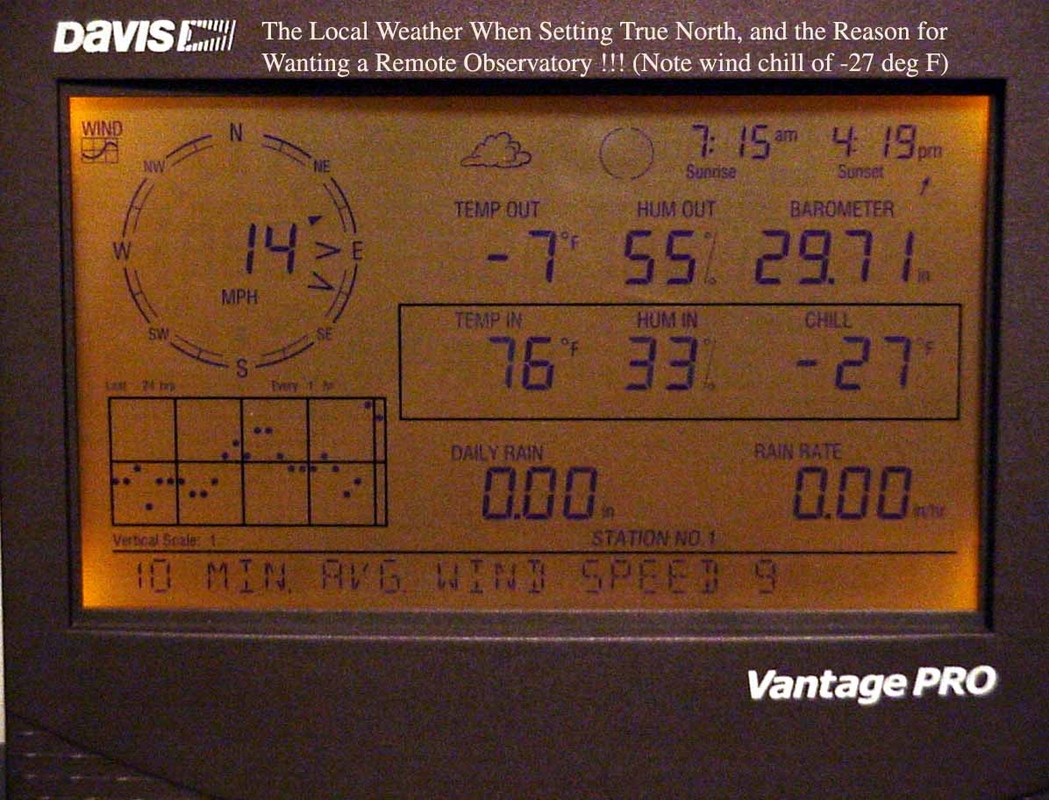
Well, we were ready to pour the cement and, by coincidence, we had a Star Party scheduled. Both were temporarily postponed. For some reason, Paul and Dave thought that -27 degrees F might be a bit to cold for pouring. As for the Star Party, with the usual gang of kids, I thought it best to hold off for a while. I shot this image of my "Davis" weather station, which is about 20 feet from the observatory site. Note the wind chill reading. Amazingly there were a few, including Dr. George Glass (a real amateur astronomer who can find just about any object with his binoculars...his computerized telescope is hard wired in his brain), and his son, who still wanted to meet !!
|
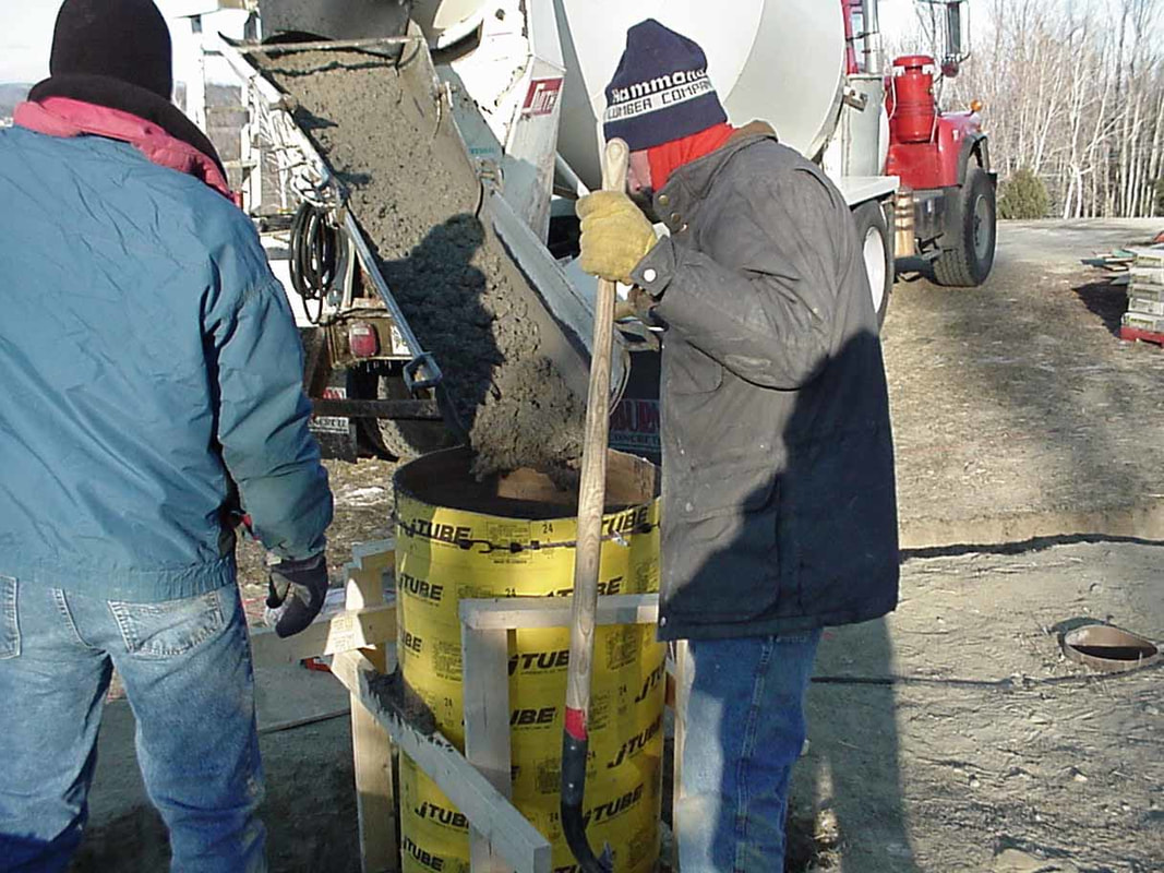
For some reason, the actual moment of pouring the cement was one of the more nerve racking from my perspective. The forms were filled with rebar. As per the concrete company's recommendation, all was at least three inches of the edge of the sonotube. The concrete was mixed with fiberglass and mixed for setting at cold temperatures. The actual pouring happens rather quickly and care needs to be taken that the sonotube is not disturbed and that the concrete is well dispersed. We were able to pour it all at once, as, despite my concern, the concrete in the sonotube was not heavy enough to push out the cement in the base of the foundation.
|
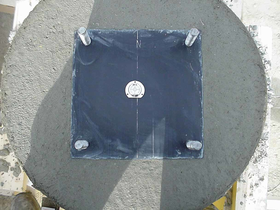
Once the cement was leveled at the top of the sonotube the mounting plates, J hooks down, were placed. A string was run along the previously marked N/S lines on the sonotube (small nails placed). The outside of the sonotube was also marked (as the inside was filled with cement !!). The plate was centered and the previously scribed line on the plate was exactly aligned with the string. The process of keeping the plate level continued for about three hours. The Software Bisque level was very handy and is clearly much more accurate and sensitive than the standard carpentry levels. At the moment of the suns' transit, at 11:53 AM on 12/30/04, the mounting plates were again checked and the shadow ran exactly along the scribed line of the plates (I was almost afraid to check).
|
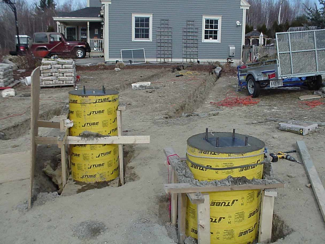
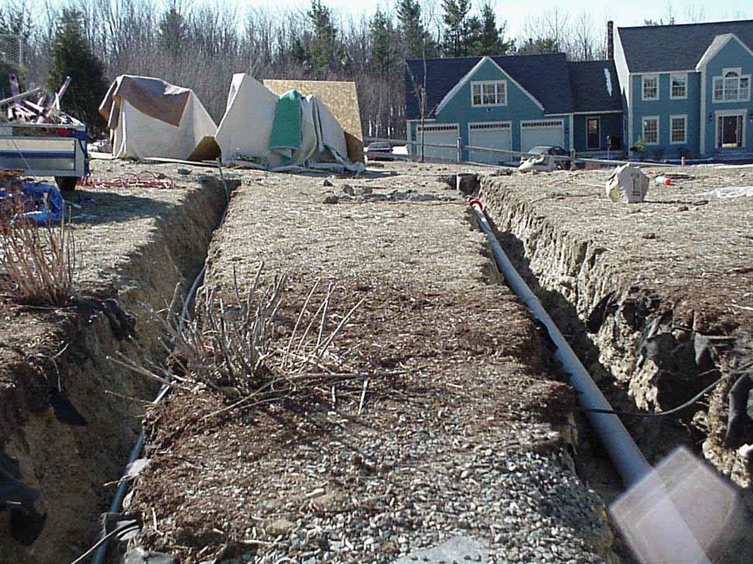
Both sonotubes complete. As can be seen, 18 inch deep trenches run in the background from the future north end of the building to my garage. In Maine, 18" is required for the outside electrical lines. Note the electrical and computer lines will be in separate trenches and are over 2 feet apart. Since the electrical is shielded in metal conduit, this is overkill, but I don't want to risk any problems with the power lines interfering with the network (ccd images, autoguiding data, etc). I saw this happen first hand in my houseside observatory, and it took me several hours to track the problem down.
|
There's Paul (right) and Dave Murphy, of Murphy's Construction (in Lewiston, Maine). Paul specializes in renovations and unusual projects. He has assured me that this more than qualifies as an unusual project (I can't image why...). He's been in touch with Brad and Wayne from SkyShed (www.skyshed.com), and we've decided to put our custom SkyShed on a deck (though they generally build a very solid structure at ground level, floor and all). Hopefully next week there will be photos of the electrical and computer lines, and a deck. Once this is done Brad will be coming down from Canada (yes, in the dead of winter) to build the SkyShed. Next the Pier Tech adjustible mounts (www.pier-tech.com) will be placed. Once placed the Meade GPS LX-200 (with piggy back Tel-Vue NP 101) will be added. Then we wait for the Ritchey-Chreiten 16" Truss Telescope being built by RC Optical Systems (www.rcopticalsystems.com), and its Paramount ME mount (www.bisque.com), both of which are expected in April. To this scope a piggyback Takahashi 106 will be mounted. There should be plenty to do while we wait. Lastly John Smith ( www.hiddenloft.com ) will be coming out to fine tune the setup and correct all our mistakes !!
|
For the computer/low voltage lines we ran 3" PVC conduit. Although large, it was easier to run the lines through them, especially since all the lines are run in duplicate (just in case). The electrical was run in by PVC to code (and therefore inside run through metal conduit). The trenches are 18" deep (electrical code). Note that the power lines remain at least 2 feet from the computer lines. Low voltage lines, such as those which will turn on the servo which will open the roof, are run with the computer networking lines. In the near future a modified diagram of the circuits will be added to the site, which will hopefully make sense out of the lines.
The blankets in the background are covering the two piers which were poured two days ago. There are high voltage lights inside to keep the piers from freezing while the cement dries.
|
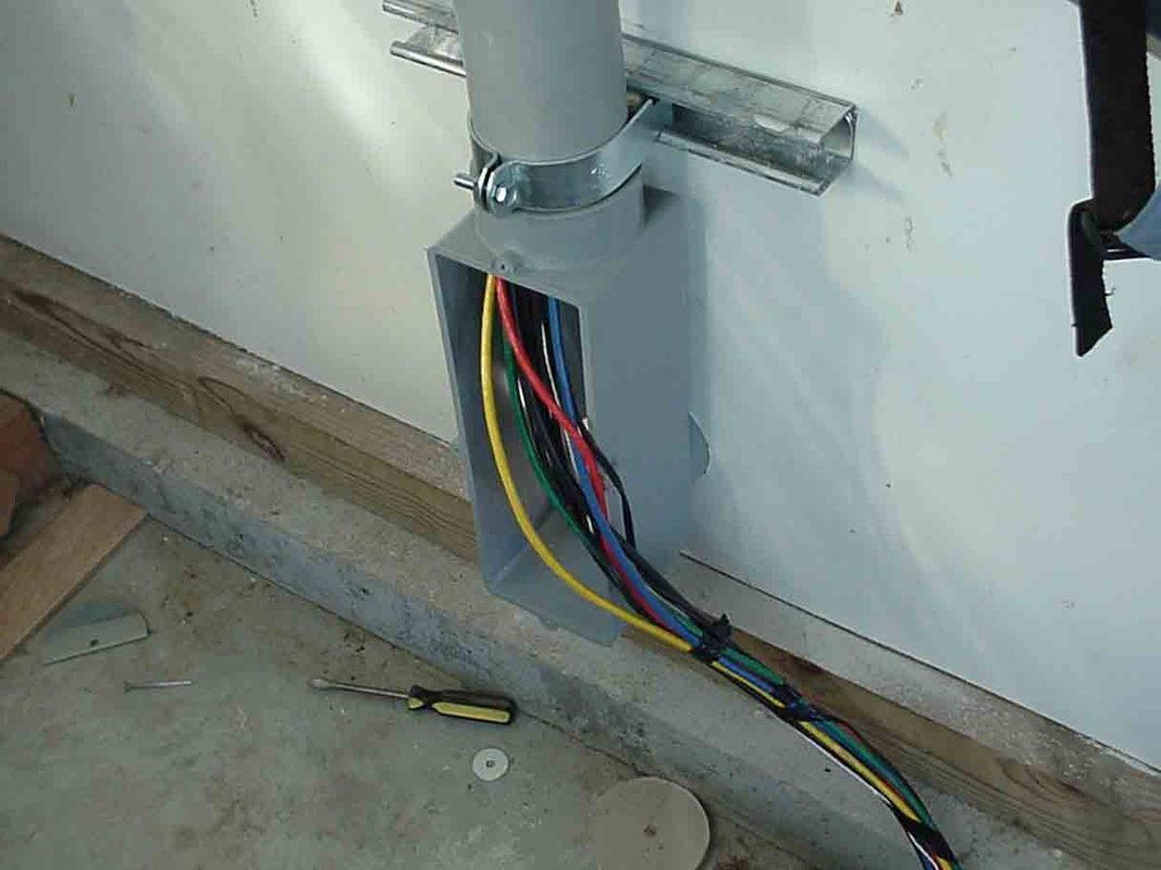
The large junction box with a removable back was used inside and outside, making it easier to pull any future wires through. This is not as easy as it seems, due to the distances, angles and number if wires. We used two network category 6 wires (color coded), 1 telephone wire, one low voltage wire and one coaxial cable. In our case all wires (except the telephone wire) were duplicated in case of failure. This amounts to a large jumble of wires which can be difficult to feed; as will be seen.
|
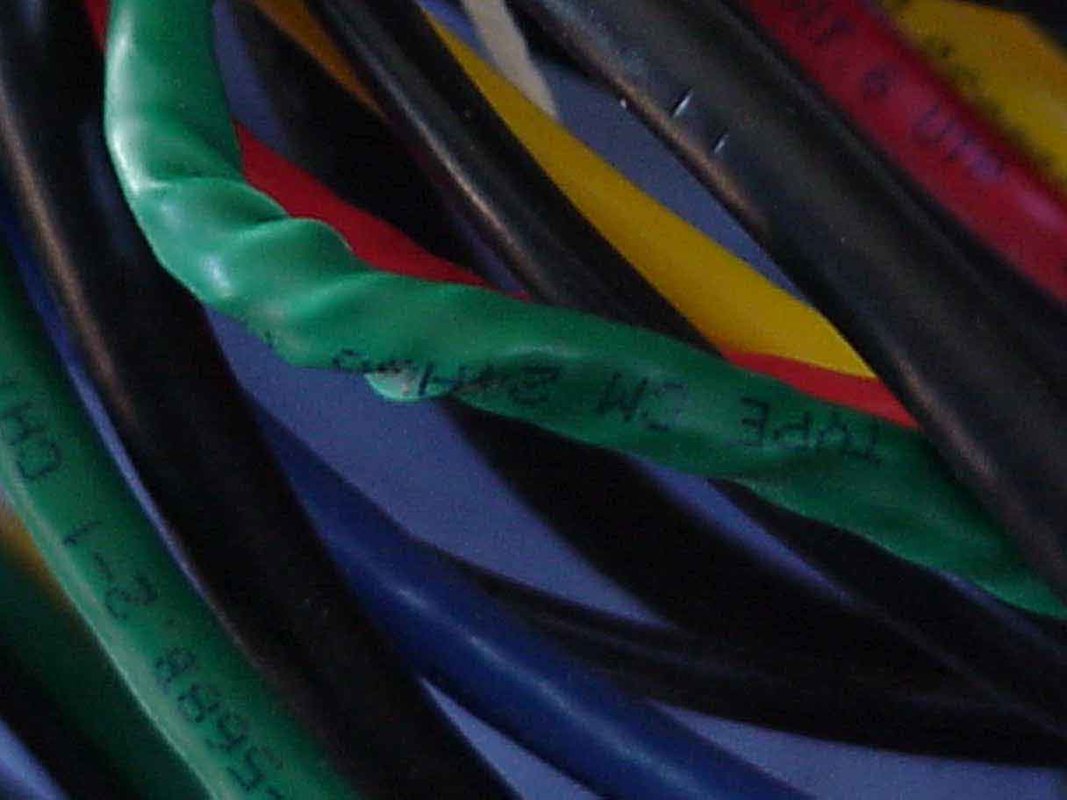
This is one of those things you never forget, and can't believe you didn't know. The photograph of the twisted wire is, of course, the punch line. What you DON"T want to do, when feeding long multiple wires, is what my son (Greg) and I spent three hours doing. We ran the first 25 feet from the remote observatory (in the house), and then through the attic to the point where the wires enter the conduit (and then travel through the garage and outside to the observatory). We had 9 sets of wires still attached to their spools at the point where they were to enter the conduit. Each wire was then taken off the spool (one big twisted mess of wires with a curve still built into them) and the whole lot was then pulled through the conduit (trust me, you can't easily get them through one at a time). As we did this the wires tended to spin and twist (ie, remain in the state they were in when they came out of their spools). Despite hours of trying to 'untwist' this jumble of wires while working in a confined attic space, we could not keep the green cat 6 wire from twisting (as can be seen, quite badly and possibly with internal damage). Obviously the green category 6 wire will be used as a last resort. Bottom line: 1) first run your wires out, untwisting them as you do, then tape them all together and run the lot as a single "bundle" and 2) run duplicates.
|
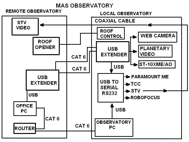
It seems only right to go over the basic networking setup and wiring diagrams. The ideas come from John Smith, and the results of this method are evident from his impressive website. This diagram is simplified and still a bit hard to read (download to improve readability). Basically the remote observatory can, via a desktop computer (using XP Professional) run the local observatory whereas a laptop in the local observatory can run the show via networking (via the router) with the main computer in the remote observatory. The USB output of the desktop computer in the remote observatory is converted and carried over Cat 6 cables and then reconverted on the other end, either to USB or to serial (RS232), as needed (conversion in needed due to the "5 meter limit" of USB, extending it to over 100 meters if needed). The lcoal observatory will require USB for: 1) a web camera to see the inside of the local observatory (If the roof is not fully open the RC-16 will move from its 'parked' position and slam into the roof. This would not be a good way to start the eveing), 2) the planetary video camera (currently using Meade's LP-1) and 3) SBIG's ST-10XME/AO for CCD imaging with the RC-16. The USB signal will be converted to serial (RS232) for: 1) the Software Bisque Paramount ME mount (for the RC-16), 2) the TCC (RC-16 telescope control center, including temoerature adjusting microfocusing and heating for the secondary mirror), and 3) the SBIG STV. Althought the SBIG STV Remote Program works well, the video output is very slow using the computer (the downloads are not real time) and therefore there will be a video link back to the remote observatory. As John has explained to me, this may seem a bit daunting for those of us without a solid computer background, but this does simplify the setup, allowing the RC-16 to be controlled either locally (in the outdoor observatory) or from the remote observatory (ie, in my home). At star parties, members could use the telescope using local controls; for visual, ccd or video purposes. Additionally, the entire setup will be robotic and can be fully operated from the remote observatory (a big plus in the dead of winter).
|
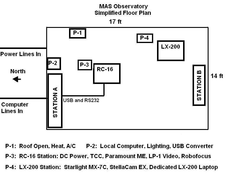
The "Simplified Floor Plan" may be a bit difficult to read and can be downloaded to better view. The SkyShed will be (at least) 12 x 16 feet with two basic telescopes as shown (both with piggy back 4" refractors). We're considering increasing the size to 14 x 17 ft (to allow for a little more room during star parties). The power to the SkyShed will be controllable from the remote site using "Smart Home" technology (Powerhouse X-10). The 4 individual power stations are described and will allow for local or remote powering up of the building, individual telescopes and work stations. There should be enough room for several people, making the observatory useful not only as a robotic observatory, but also as a teaching facility. This last point is crucial to the purpose of the Maine Astronomical Society and is the reason I opted for a larger structure.
|
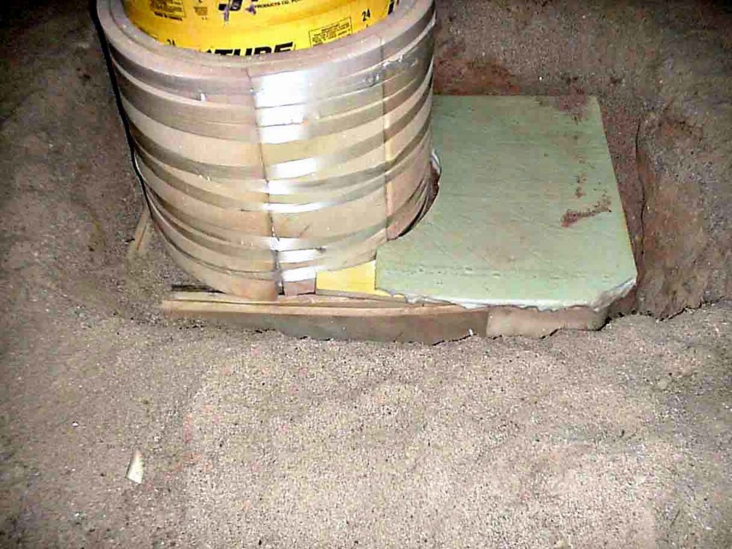
A good deal of thought went into the foundation of the telescope (whether effective or not, time will tell). And though this picture may not be pretty, we're hoping it will further minimize any pier movement which might occur during the winter. This is the pier just before the last two feet were buried. The foundation of the pier begins 5 feet underground, with the sonotube sitting on the top of the foundation, beginning 1 foot under ground. The top 2 feet (ie, the first foot of the sonotube and the top foot of the foundation) are wrapped in 2 inch foam. The reason for this is that the top two feet is the usual depth of our winter frost line. The hope is that by doing this we will minimize the effects that the earth along the frost line might have as it push/pulls on the top two feet of the pier. Granted, it is unlikely that the frost line would cause much movement as the foundation is 5 feet deep and further secured by rebar pounded 2 further feet into the gound (ie, total depth of 7 feet). But considering my previous experience (the telescope on a deck) I figure its better to be a little overly careful. John Smith, our consultant, sitting in his 70 degree Arizona winter weather, got us going with this as he was concerned about potential effects of the frost line (do they even have frost in Arizona ??).
|
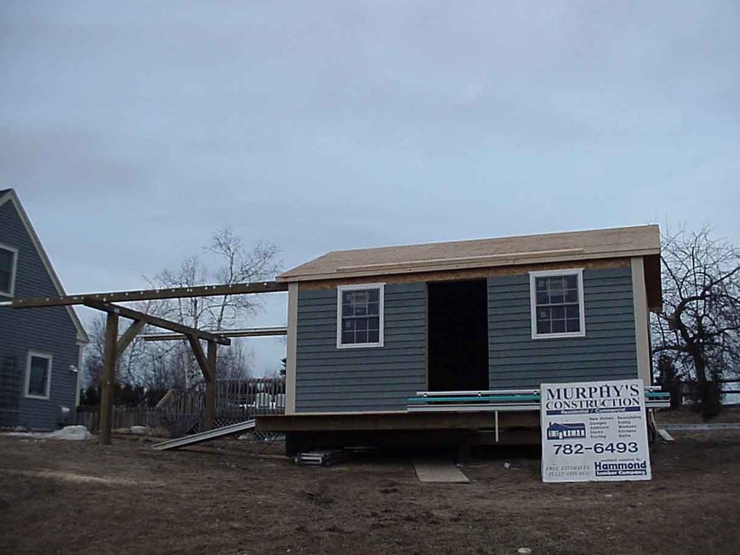
I can't think of anything better to say here except that we've gone from a 10 x 10 foot structure, to a 12 x 14 foot structure and now up the 14 x 17 foot platform you see here, with a 3 foot wide deck on the west end. I figure the bigger the structure, the better off we'll be at star parties (John Smith wants to know where the billiard table will go...). The down side is the logistics. Brad at SkyShed agreed to this size, though they usually keep the width to 12 feet (the largest 'standard' size for their roll-off shed design). Expect the construction to move fairly rapidly at this point.
|
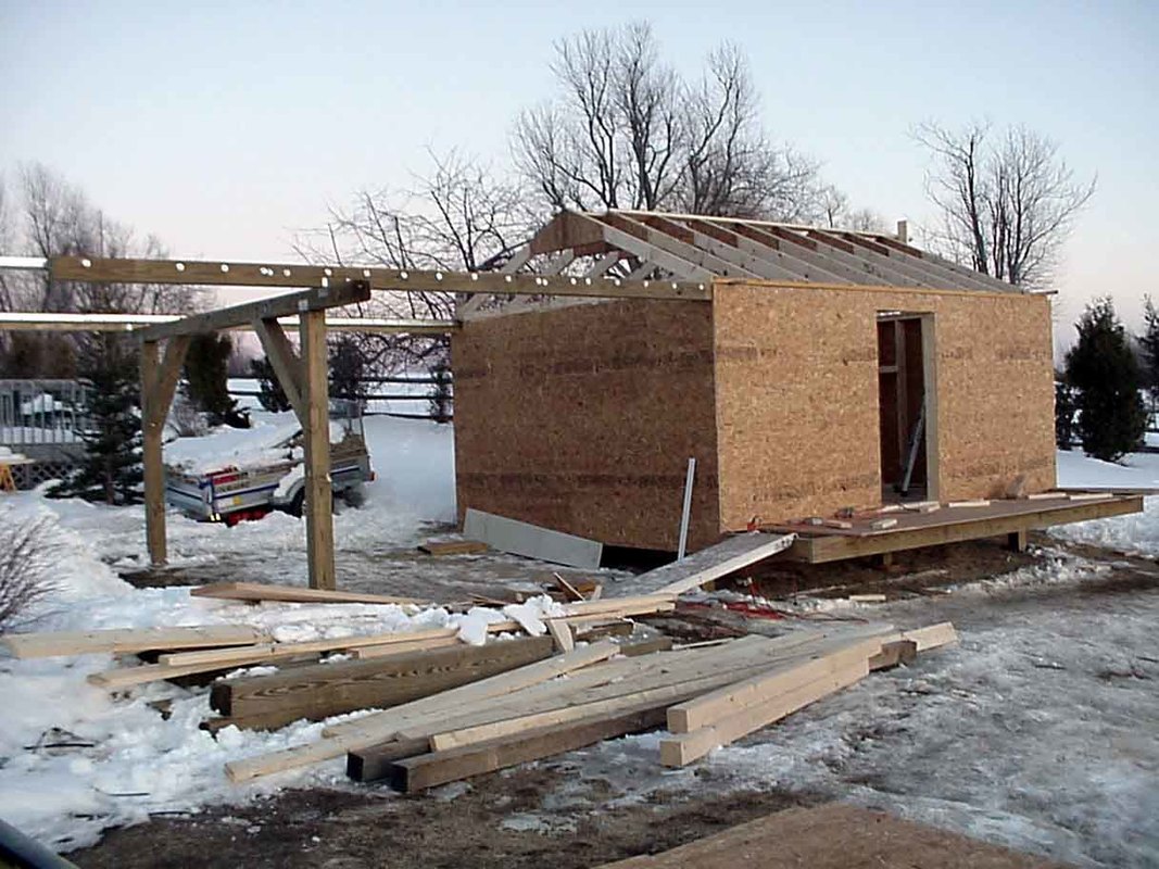
At this point, as can be seen, the basic structure, minus the sliding roof, is up. A small deck is present in front of the structure (steps and rails will be put in place). The rails are sturdy, are 6 x 6 in size and held in place by 6 x 6 posts which are on 4 foot deep foundations. This is a variation from the original SkyShed design, done because of the increased size of our observatory. As I'll reiterate again and again, I highly recommend obtaining the SkyShed design CD, or having them build the structure for you (if you're close enough to Toronto). They've put a lot of time into their construction CD and it points out the many pitfalls which can ruin an observatory. They've not only put alot of time into how to build the basic structure (including telescope foundation), but have a clever and effective design for the sliding roof, the most critical part of the structure). The company can also send you a kit with all the "hard to find" items and they even have detailed list with part numbers, so one can go to Home Depo (or similar store) for the parts. I believe they'll have an automatic opener included in their plans in the near future (ours is self designed with help from Brad at SkyShed and Paul Murphy, our carpenter).
|
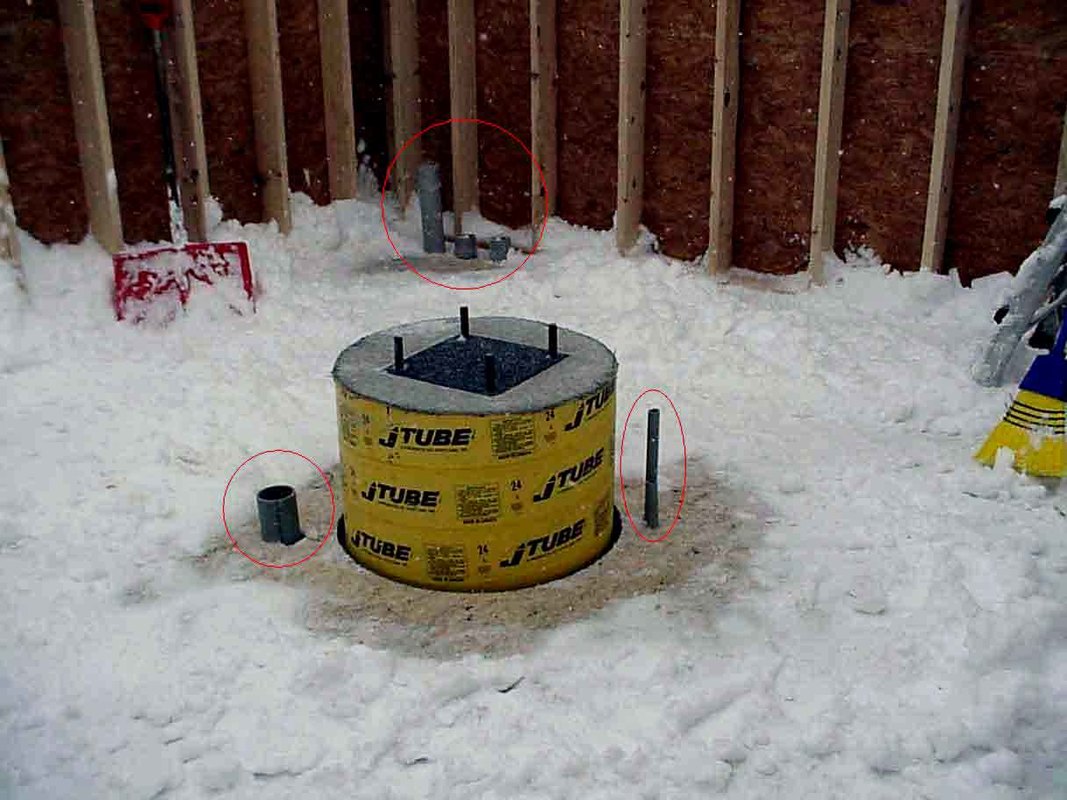
The computer lines (3" sonotubes; just in case I have to run a parallel connector) and the electrical lines (1") all run underground to the house and then under the floor. In the far corner three 3" conduits can be seen (circled in red). The one on the left will carry all the computer/low voltage wires into the structure from the house (which contains the 'office' which is the remote observatory from which everything can be operated) and the other two 3" conduits go to the RC-16 scope and the LX-200. The computer lines and the electrical lines to the RC-16 can be seen in the foreground, with the red circles around them. Neither touches the sonotube and, as usual, the electrical and computer lines will enter the scope from oposite sides of the sonotube.
Also note the 2 x 6 construction. This differs somewhat from the Sky Shed design, and was done because of the large size of the structure (not to mention the fact that we frequently get hit by 40 - 60 mph winds from Mt Washington, which still holds the record for the worst weater conditions in the continental United States). SkyShed's, which use 2x4's, have been hit by major blizzards and have evidently all have held up well (we still like the 6x6 design in view of the size of our observatory). Our walls and floor are of a composite (weather proof) materail and painted clapboard (to match our home) will be placed over this. The ability to use the SkyShed CD plans for many ideas and yet vary from the design is another one of its many strengths. In our case the size and weather conditions prompted us to make modifications, including 4' deep pilings for the structure and rails and 2x6 walls with a 6x6 rail. This has added significantly to the price. For any structure 14x12' or less, I'm confident that the SkyShed design, as it comes on their CD, will do the job well and be much less expensive to build. Again, I'd strongly recommend contacting SkyShed at www.SkyShed.com before proceeding.
|
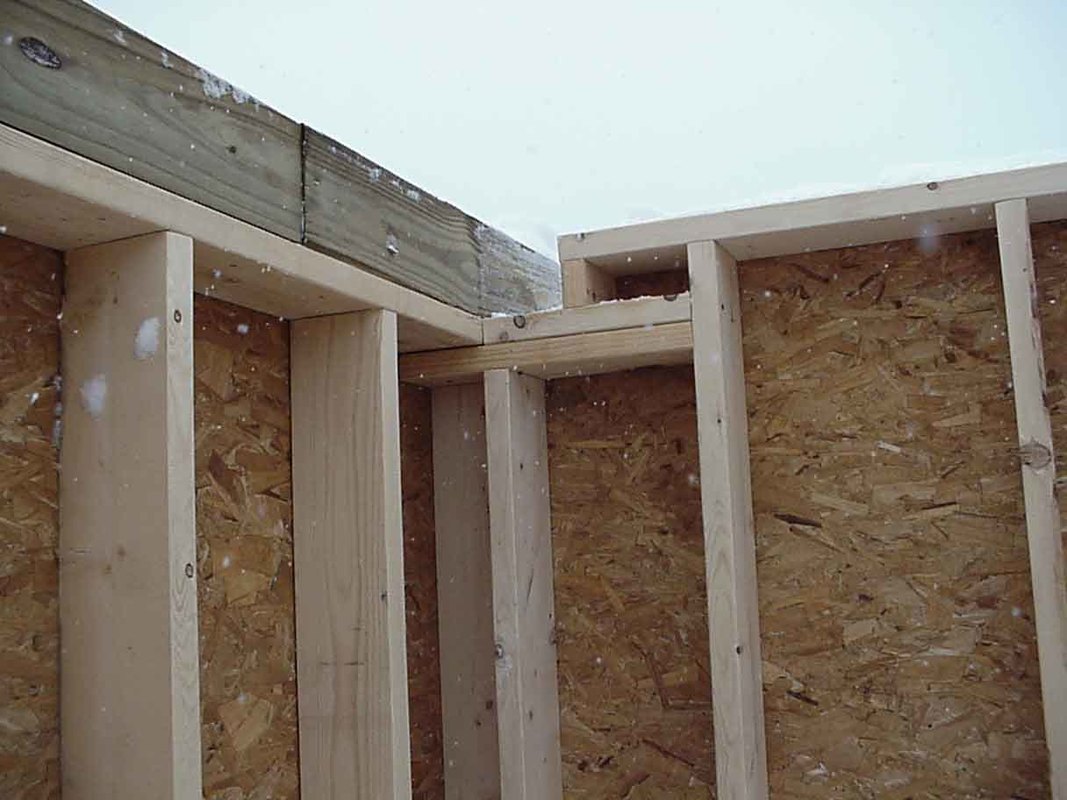
This photo shows the northwest corner and is important from a structural perspective. Again the 2x6 frame and 6x6 rail can be seen. One example of the type of detail SkyShed cares about can be exemplified by way the rail is cut over the structure itself, and not at the edge of the structure (where, over time, an cantilever effect could significantly bend the rail and effect the roof sliding performance). They have dozens of key points in their CD, problems they have encountered, solved and detailed, so those of use who plan to build just one observatory can avoid. They also have a clever design for attaching the roof to the gliders. For those type of details I'd recommend their CD. If this recommendation isn't convincing enough I'd recommend you check out the article detailing their "Polaris" award from the Belmont Society. This can be viewed at www.belmontnc.4dw.net/skyshedcd.htm and discuses the many merits not only of their design but also the method in which the CD displays the construction process (slide show with rotating 3-D schematic views, detailed technical notes, etc).
|
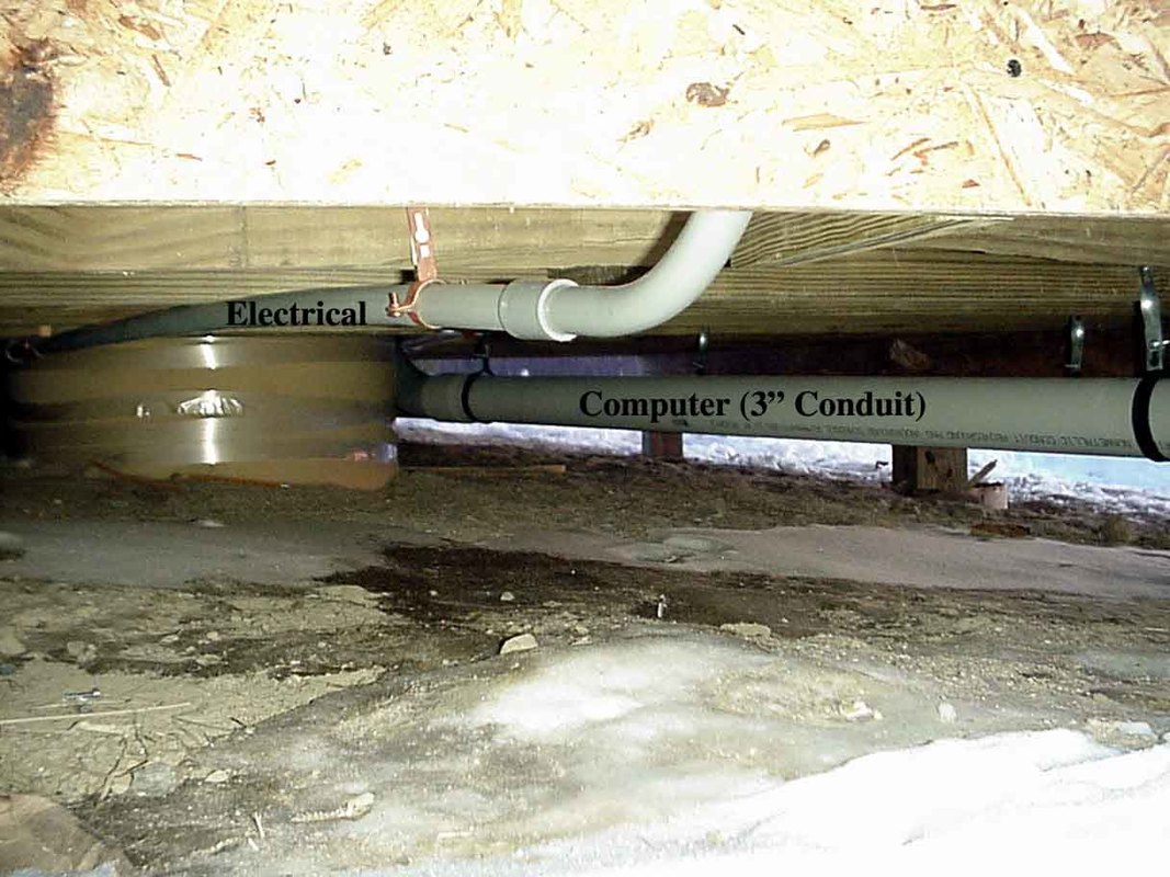
Beneath then observatory electrical and computer conduit lines were run as previously described. Hopefully fewer people will trip over the lines or accidentally pull them out of the telescopes this way.
|
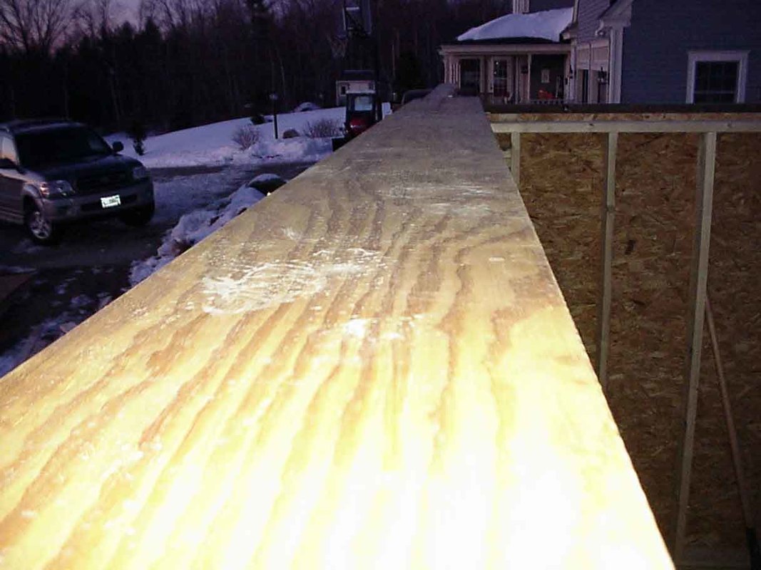
This laminated and absolutely straight 2 x 10 was quite expensive, but, as Brad from SkyShed pointed out to us, this is not a place to skimp and save. If this piece warps, then the entire roof (which sits on top of this) may not open, especially with a larger structure.
|
View of the roof framing up and on the glider and wheels. The silvery dots are the multiple bolts placed to secure the glider. Many were used to insure that the glider would remain aligned.
|
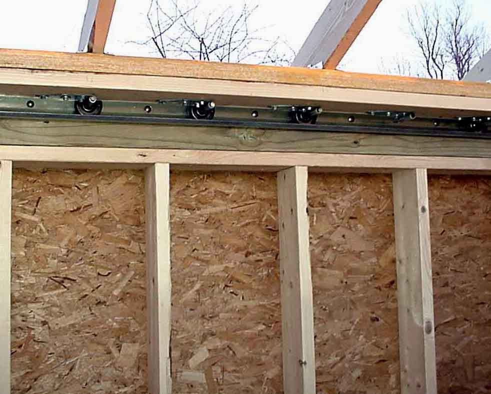
Overview of the roof framing on the laminated wood which in turn is attached to the 3" wheels and industrial strength glider. This structure can be easily moved with one arm.
|
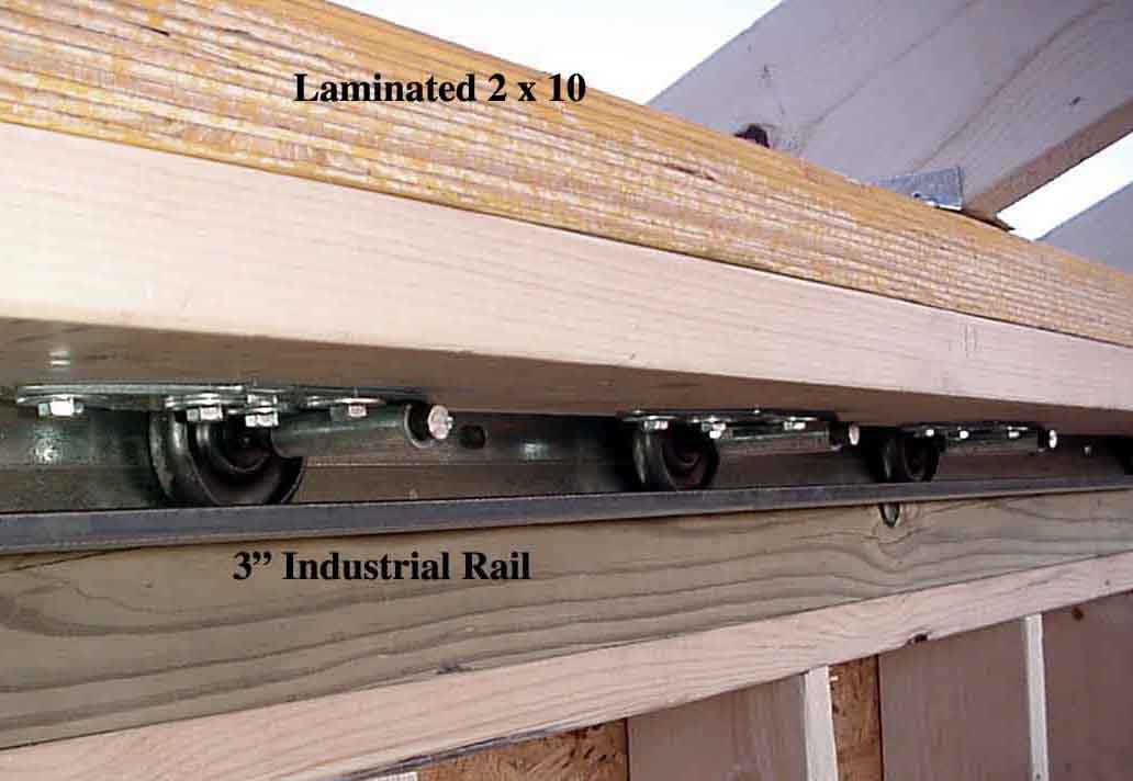
The 3" wheels and glider can be seen. The details of how to assemble this correctly are nicely covered in the SkyShed Plans. Had we not used these plans I am confident we would have had serious difficulties (fortunately we decided NOT to try and "re-invent the wheel"...as its already been invented and is on the SkyShed plans).
|
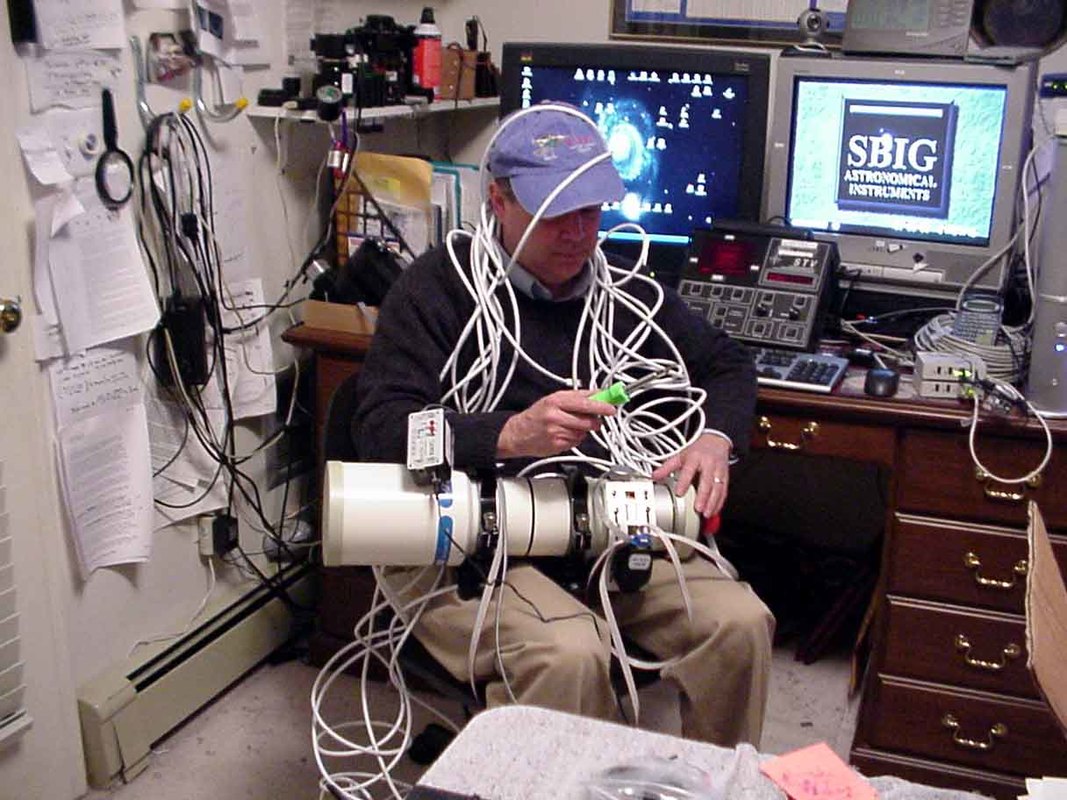
So while we're working on the observatory I've been trying to get all the wiring straight. Got to get the router to the PC, the LEX/REX Icron to the Edgeport, the Cat6 wires to the observatory, the remote settings on the desktop, configure the edgeport, adjust the temperature coefficient in the RoboFocus.........Truely, I have no idea what I'm doing..........Now where did I put John's phone number......
|
It's beginning to look like a roll off observatory. The structure was basically built using the SkyShed design with modifications for its size and also to match the look of our home. Inside there are now 7 controllable plugs (X-10 Smart Home devices), which will allow us to remotely power 7 systems on or off (lighting, roof opening device, heat/dehumidifier, web cam (is the telescope in the parked position when I open the roof !!), RC-16 systems (Paramount ME, ST-10XME, observatory accessory computer ((which can remotely control the main "office" computer)), and Meade GPS LX200 systems. This can be done from inside the observatory or remotely from the "office".
|

Gray aluminum roof (won't hold heat, light weight and trouble free) in place. Roof is open and the south drop down (seen on the right) is open. This will be great for my favorites, such as Sagittarius and Serpens Cauda. The motors for both are still being discussed. We're favoring a rack and pinion method or "Miracle" Drive (self propelling wheel within track). More on this in the near future. The South drop down will have a separate drive as it will be used less often.
|
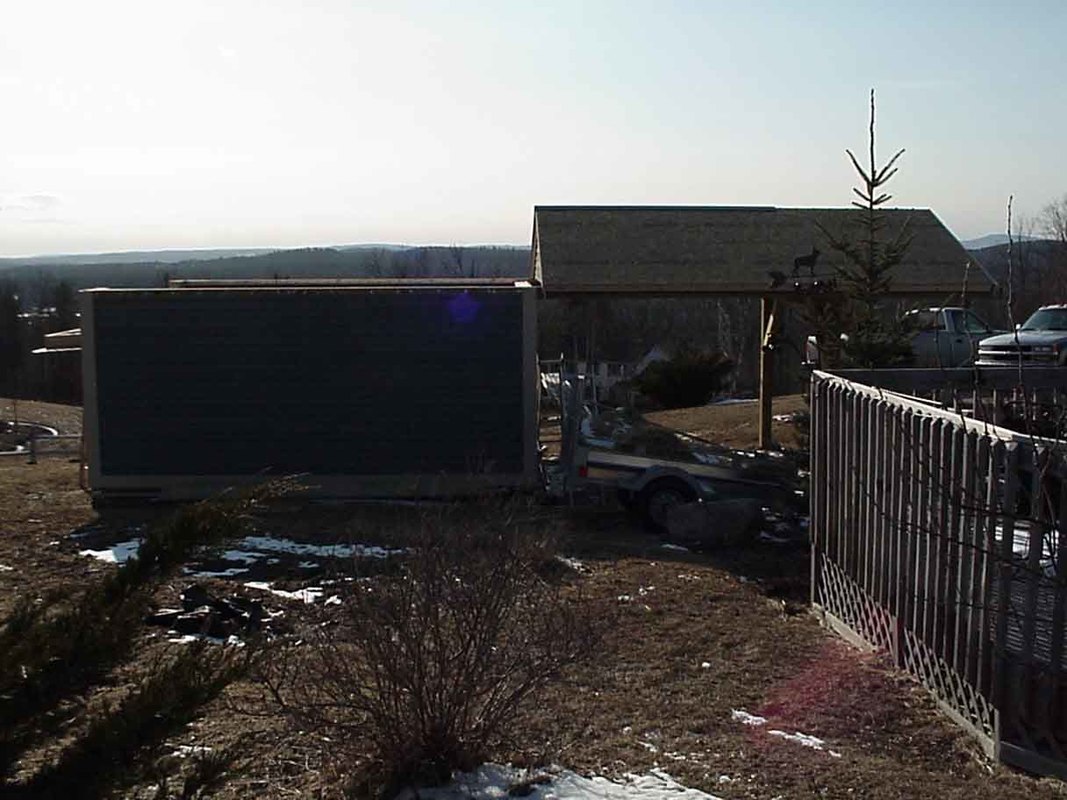
Same, only looking from the east towards the west; the roof not quite completed on this side. The drop down can be seen on the left (south).
|
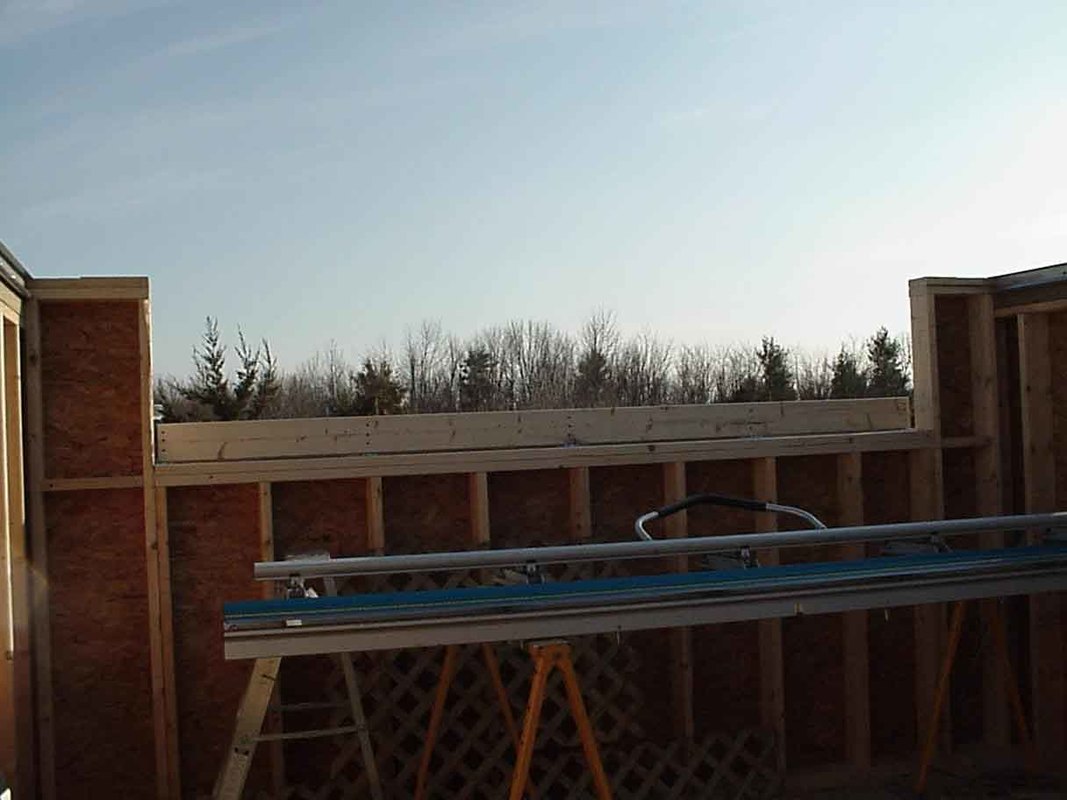
This drop down has hidden hinges beneath the clapboard, so that the observatory still appears to be just another Maine "shed". As can be seen, this will allow us to photograph those southern constellations with all their treasures. This will be a great area for the Tak 106, e.g., taking wide field views near the heart of our galaxy in Sagittarius. In order to eliminate as much ambient light as possible, this will kept in a closed position most of the time and, therefore, we're going to put a separate control on the drop down.
|
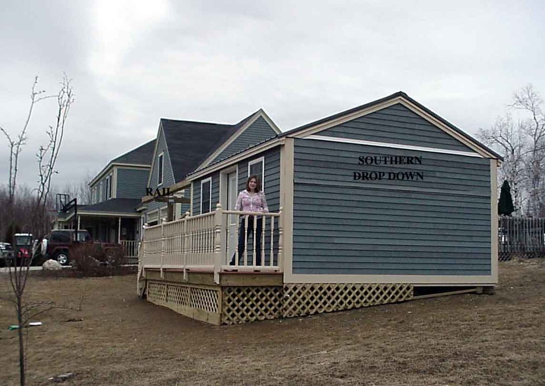
The outside is nearly complete. The Southern drop down can be seen on the right. My daughter, center, has finally shown some interest in my hobby (it lasted about 2 minutes). For some reason she thinks my hobby is "wierd". We've decided on a "trolley" type system to open to roof. It is a 1/2 horsepower system built for outdoor or indoor use, with remote settings and safeties available. It looks sturdy and those who will be putting it in ("Bob's Overhead Doors" in Sabattus, Maine) have done so many times (a big plus if there are any problems).
|
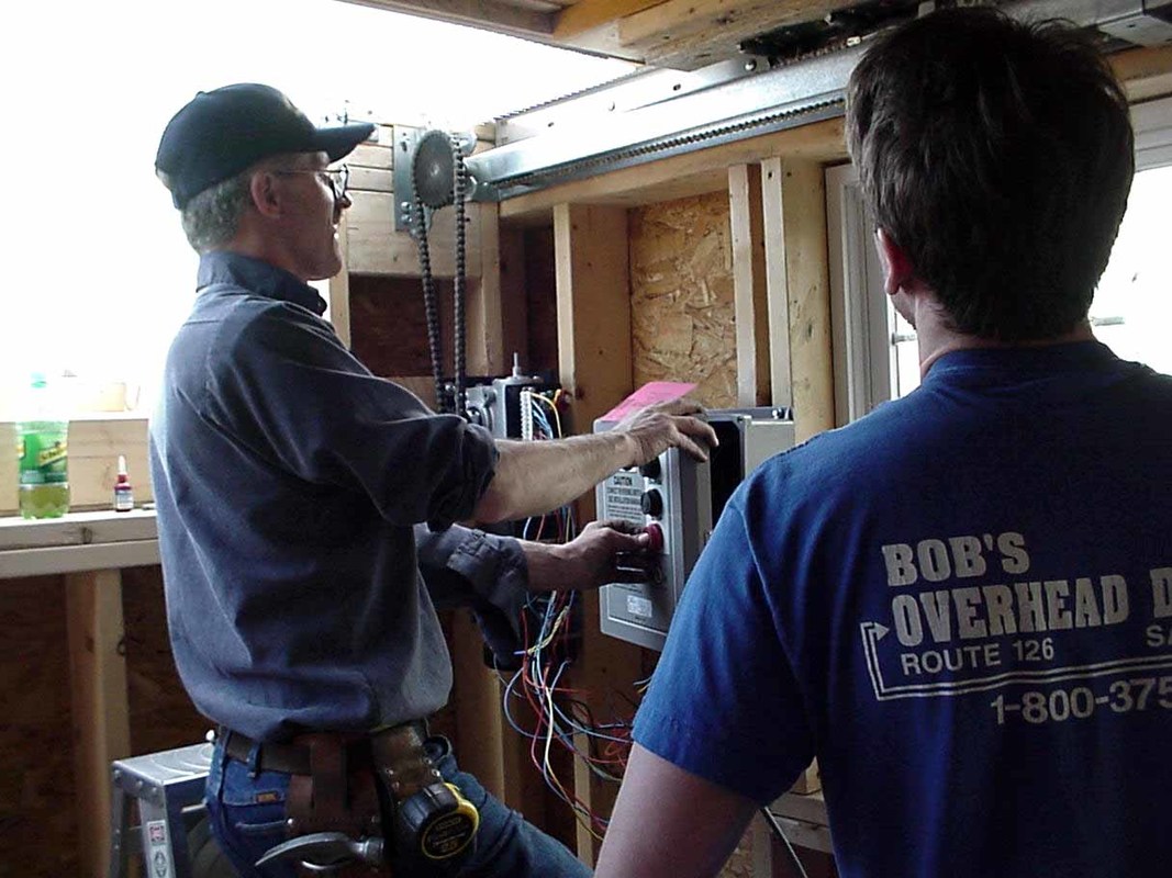
There's quite a bit to point out here. The first is to find a garage door specialist in your area, someone who will enjoy an unusual project. Our final design was a commercial water-proof system (Liftmaster; Model EGJ: "jackshaft carwash opener". Details of the model can be found at www.liftmaster.com ). We used the "optional through-shaft" configuration (described in the manual). The opener pulls a standard "trolley" attached to the roof, which rolls on the 2" wheels. We disabled the timed "stop" points, as they weren't reliable enough. Instead our system has automatic water tight servo's at the fully "closed" and fully "open" positions (and "back up' hard stops {heavy duty bolts), so that the roof can not just roll off the building if the automatic stops fail). The system works flawlessly, locally and remotely. Weatherproof remote light and infrared cameras (not shown) were installed (looking inside and from the outside) so that the position of the telescope can be seen, and more importantly, so we can be positive no children are in the area when opening the roof.
|
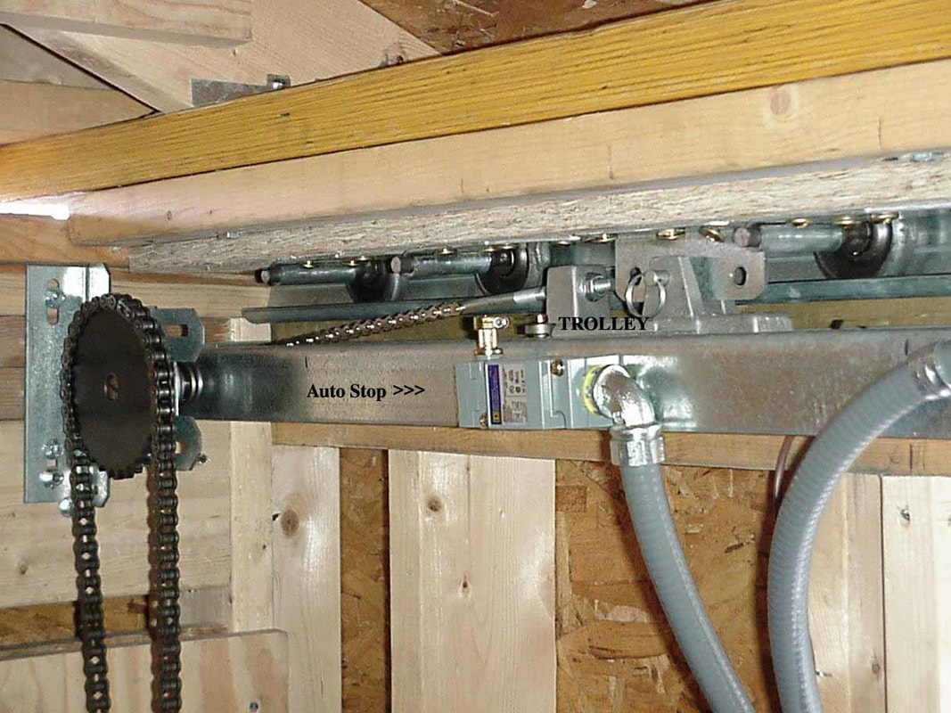
Although difficult to see, the automatic stops are visible. Most of these engines are designed to move a specific distance and then stop. The roof, however, goes beyond the general limits and therefore the "stops" were added and the distance regulating "cams" were disengaged. This system also allows us to open the roof beyond then north end by about 2 feet, which may come in handy when observing northward. Along with the southern drop down, we feel our views will be great.
|
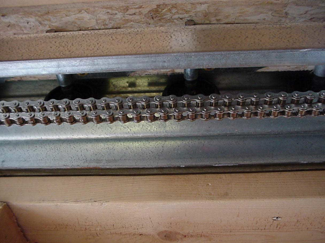
This was a nice touch by Bob of Bobs Overhead Doors. The chain is nickel plated and therefore essentially rust proof. Parts of the chain are exposed to the weather and over time rust would have been a problem. As this chain moves it pulls the "trolley", which in turn is attached to the roof. Again, we would advise spending a little extra money and having an expert do this. And if anything fails, you'll have someone who can help with the solution.
|
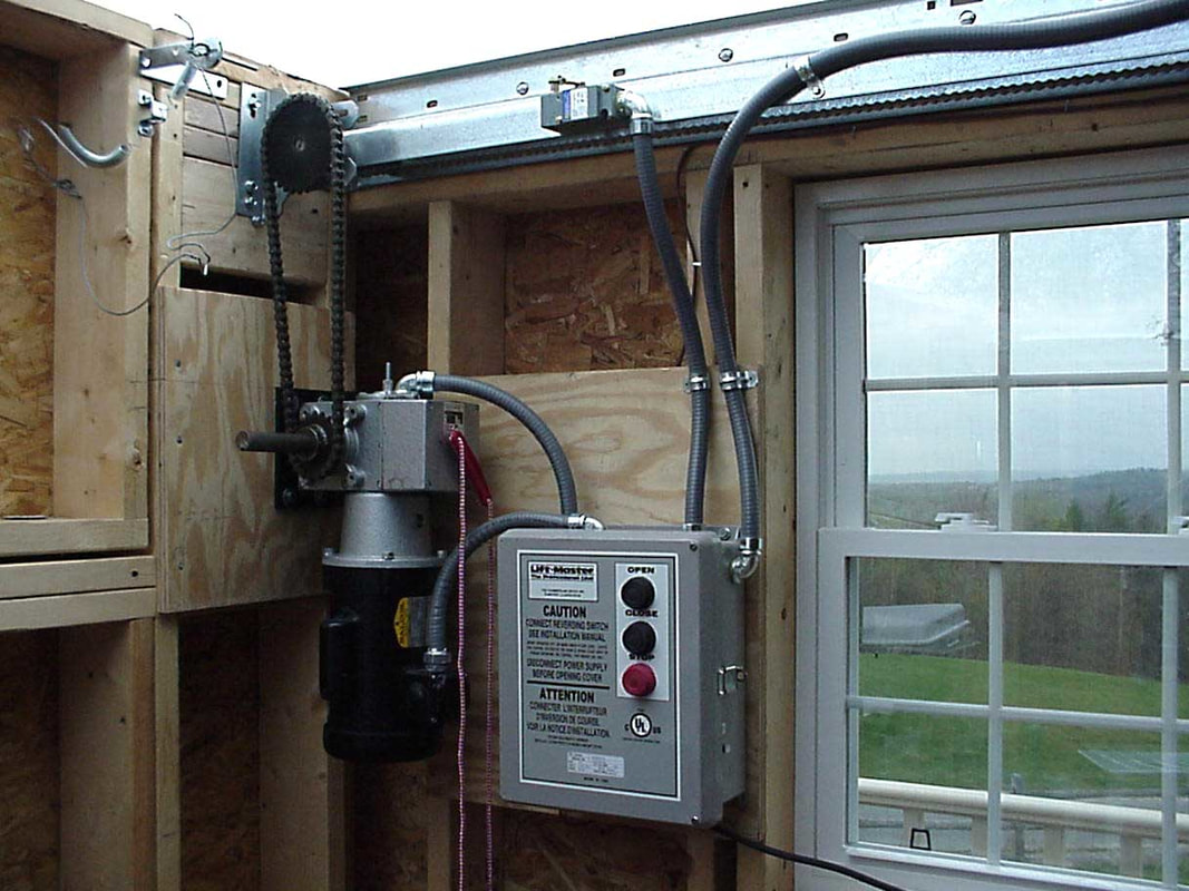
The complete control system. The gears are "stepped down" for maximum torque. In fact, we could have set it to a faster opening speed (it worked just fine). However, more torque and less speed is a safer combination. The two "conduits" coming out of the right side of the control box go to the automatic "stops". The rope is a disconnect device so we can open the roof in case of mechanism failure. A casing is being made to cover the gears (safety issue, especially with children at the star parties).
|
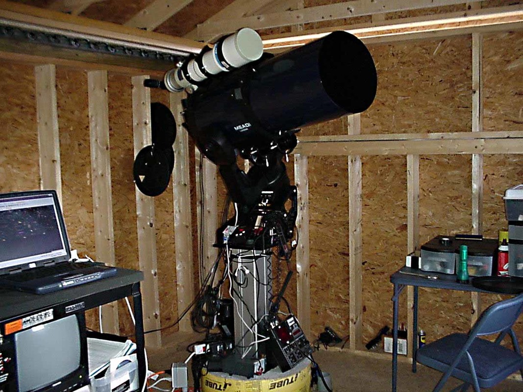
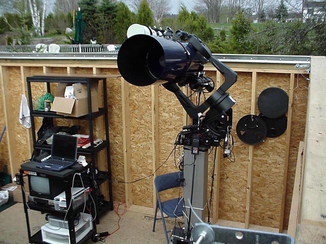
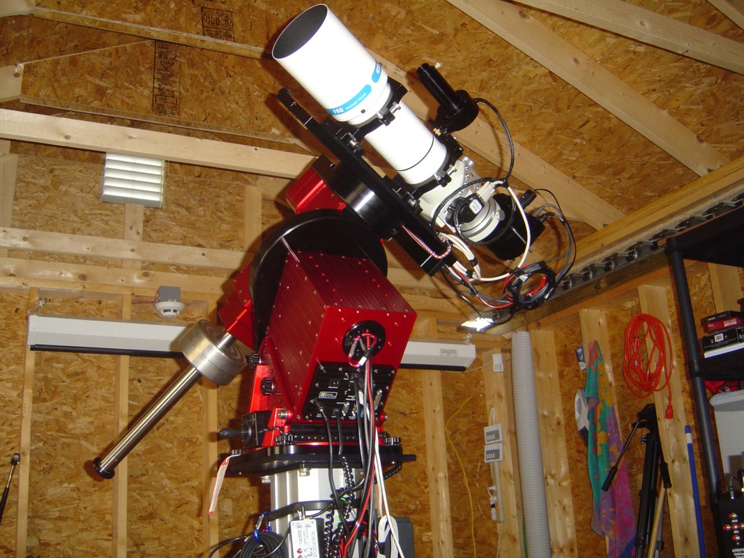
This is the first photo of the Meade robotic system in place. The same basic principals will be applied to the Paramount ME/RCOS-16 system, when it arrives. Visable is the 12" GPS LX200 with a piggy back Tak 106 refractor, on the Pier-Tech II in the lowered position. The system can be run locally or from an office (no more walking through the snow in the winter). At star parties, guests can control the computer in the office (which is directly hooked up to all the telescopes systems) by using an observatory computer which can connect (and therefore run) the office computer through a router and XP Professional software (thanks to John Smith !!). After working out a few computer bugs, the system works perfectly.
|
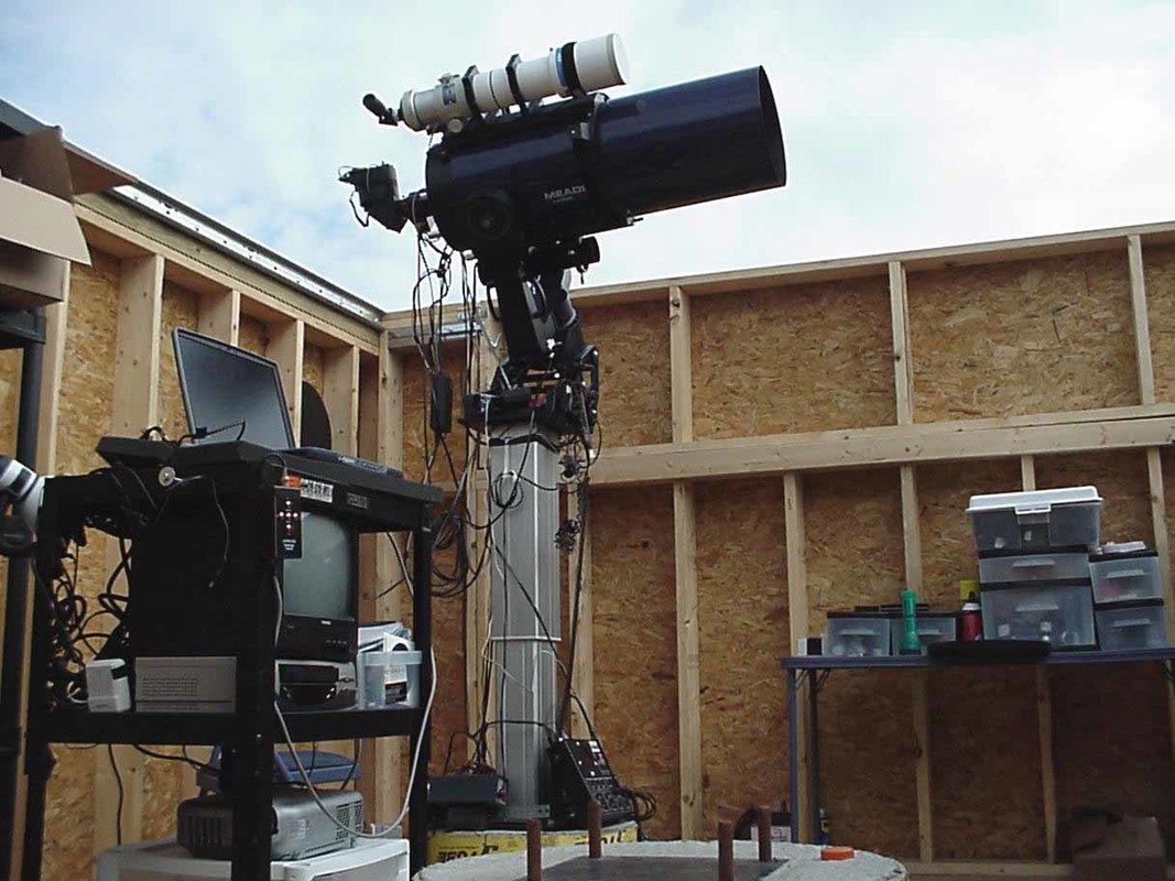
With the Pier-Tech II in the Up position we were literally able to see over the sides of the 7 foot building. Although the full height will rarely be needed we have found to ability to raise and lower the telescope is great for viewing purposes. Importantly, there was no observable difference in alignment with the Pier-tech in an up or down position (see the Pier-tech site for John Smith's studies on the remarkable accuracy of this device). Note the sonotube in the foreground, just waiting for then RC-16 !!
|
The system is now fully up and running. First "ccd" light with the robotic system has not yet occurred, but will soon. Working with the LX200 will allow us to learn to use this system and hopefully make the transition to the Paramount ME/RC-16 a little less difficult. It is hard to put into words how exciting it is to go from a hole in the ground to a fully functional robotic observatory. Every conceivable function, from opening the roof, to alignment, focusing and imaging, can be accomplished from a quiet office 150 feet away. More on the details of the computerized/robotic system in the near future.
|
This page used to have a "Real Player" video of the observatory during construction, but now displays a mpg video. The visual quality is better, but the photographic skills couldn't be much worse. It nonetheless shows some of the basic functions and layout of the observatory, PRIOR to adding the RCOS 16 inch Ritchey-Chreiten telescope. Currently the entire observatory is fully robotic (ie, all functions can be run remotely). This video can be slow to load up (about 51 MB) and you'll need a media player, such as Windows Media Player, to view this.
|
Here's a breif view of the observatory AFTER the RC Optical 16 inch Ritchey-Chretien reflector has been added. There's little to say about this video, it's just a brief view of the observatory from the roof. It has about as much artistic and technical skill as the last video (ie, none). Hopefully it will give you a sense of how the observatory was designed for both for serious astrophotography and star parties.
|
| ||||
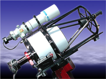
This is a photograph of an Optical Systems Ritchey Cretien telescope. This one, a bit smaller than the one we're awaiting, also has a Takahashi 106mm mounted, much as we are planning. In our case, we intend to use this refractor for wide field astrophotography. The RC-16 may be months in coming, but we believe will be well worth the wait (the primary mirror is undergoing ion milling in the Ukrainian). Go to www.rcopticalsystems.com for more information on this remarkable telescope.
|
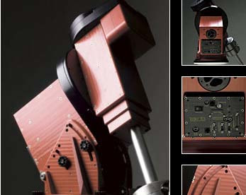
This is a photographic composite taken from Software Bisque's site (with their permission), and illustrates the Paramount ME Mount. This mount is considered by many to be one of the best, if not the best, fully robotic telescope mount available. The mount, especially when flexure and other errors are compensated with Software Bisque's ProTrack program, has allowed for 15 min (and longer), accurate guiding without the need for active corrections. This is remarkable. For more information go to www.bisque.com . Needless to say, we can hardly wait for it's arrival and installation.
|
About a week ago the Paramount ME arrrived from Optical Systems. What a gem. The Paramount ME manual is great, and the new electronics included a direct USB link to the mount. Then mount has a beaurtiful array of built in connectors, connecting the mount to the telescope through the mount itself, so you don't have to have danggling wires comming off the telescope. As an awazing bonus, the dec plate comes off, allowing several "extra" wires to go through the dec tubing. Translation: NO more wires hanging off the scope. Operation of the ME throught the SKY 6 was flawless and user freindly. I'm using the Tak-106 atop the scope to get used to using it. I'm quicky learning about T-pointing and Pro-Track. Put simply, T-pointing is the process of building a virtual reality sky which takes into account all the imperfections of your telecope. Once "applied" to your star map is improves excellent systems to arc-second acuracy (!!). Pro-Track allows you to use this information while tracking. These are professional grade tools.
What amazes me about the ME is the craftmanship. It is well designed, beautifully constructed, and appears to be mechanically perfect. It is obvious, from the moment you lay open the boxes, that a great deal of thought went into this fully robotic telescope, all the way from from packing to ease and accuracy of use.
My only recommendation would be to work on the T-Point manual. The information is all there, but it could use a bit of re-organizing and should contain a section on Pro-Track.
|
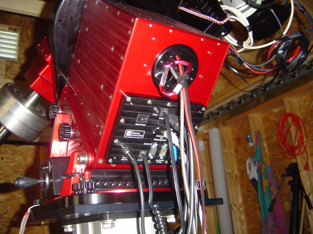
This photograph shows the "adapter panel" (large black square area) and "cable conduit" channel, which allows wiring to be installed throught the declination mount and up to the telescope (I have my STV cables, an extra USB cable, and the TCC power cable for the 'soon to arrive' RC-16 running through the conduit, with room to spare). There are multiple built in access points to the telescope on the built-in panel, including a 3 and 7 pin serial ports, autoguider port, standard CCD camera power port, focus port, parallel port, and 2 auxillary ports. As can be seen, this set-up allows for USB driver support between the computer and telescope (Software Bisque includes the necessary driver software which is easy to install). I removed the small access panel which covers the USB port to the Paramount ME (and has some delicate looking components which I don't want exposed or touched...as I have NO idea what they're used for) and drilled a small hole thru this small access panel, allowing the USB cable to exit this panel (ie, the electronics remained covered). I imagine future versions will have this pre-drilled or the USB port separated from this area. The USB drivers work perfectly. All wires run through the mount, a must unless you want to stand there all night and watch them (no thanks !!).
|
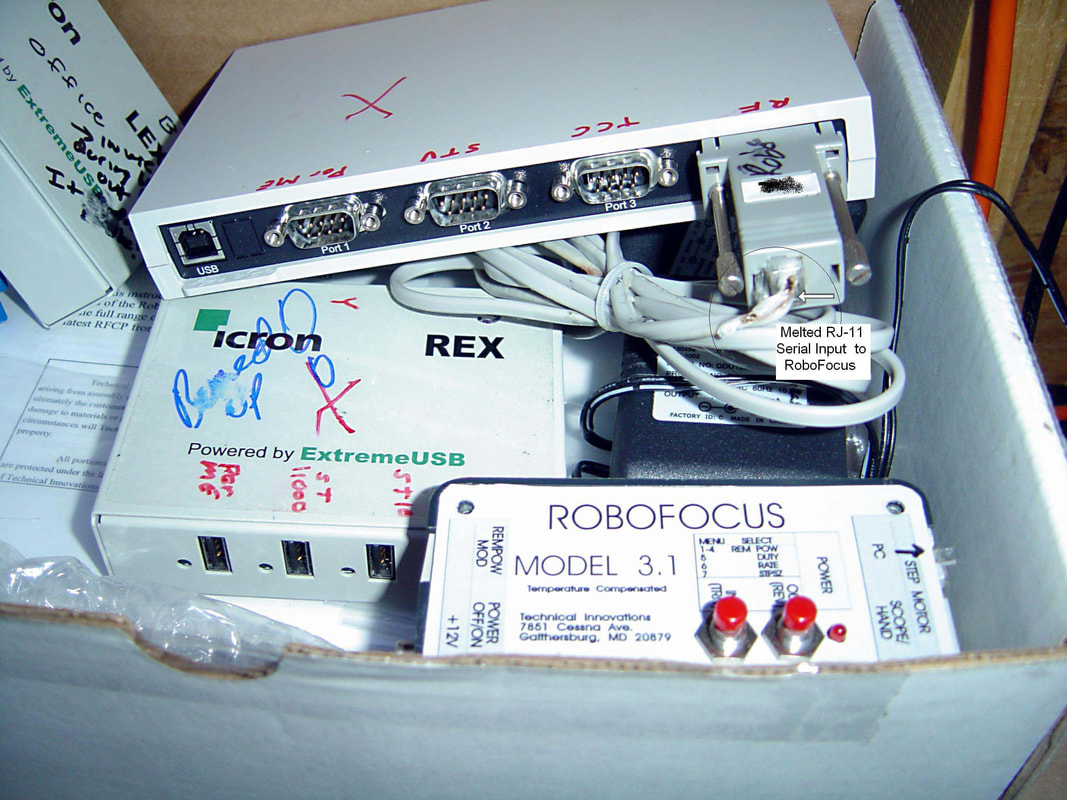
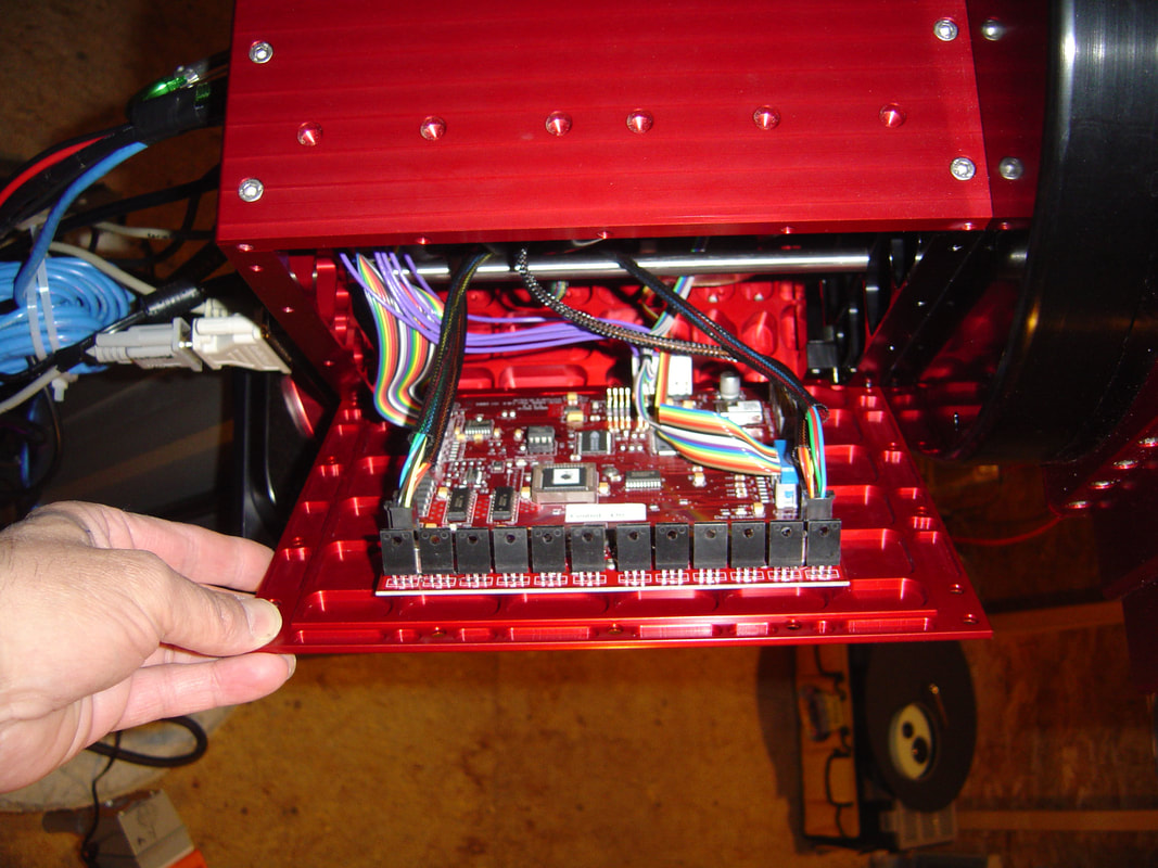
Why, you may ask, is there a box of "junk" in this image. This is one of the most important images on the website. It is what can happen if you do what I did, ie, make a wiring error which results in an electrical fire, which in turn can (and did) cost hundreds of dollars and many stressful hours to correct. In this case you'll note the Icron Ranger (on the left, and carries the USB signal, via a catagory six cable, the 150 foot distance from my office to my observatory). I attached the power to it briefly with the polarity reversed. When it didn't light up correctly I reversed the polarity and all seemed fine (ignorance is bliss...). Unfortunately the Icron Ranger was evidently damaged when it was powered with reverse polarity. Within 10 minutes I saw SMOKE billowing from the side of my telescope (yes, the beloved RC-16 !!). I powered down, recovered from my heart attack and found that, as best as I can figure, the damaged Icron Ranger had sent a higher voltage to the Edgeport (which normally converts the USB signal into a serial signal for some of the telescopes components) and the Edgeport transferred this current into the RoboFocus which proceeded to SMOKE, BURN and MELT. Little did I realize that I ALSO damaged the DC voltage input to the SBIG STL-11000, the USB input to the Paramount ME, the TCC (telescope control to the RC-16) and, of course, destroyed both the Icron Ranger and Edgeport. It took me 2 weeks of daily (after work until 2-3 AM) work in order to track down what had happened. As always, Brad and Dan of RCOS came through with a new TCC. The last repair, of the Paramount ME mother Board, is shown in the next image. LESSON: DO NOT USE OR CONNECT ANYTHING UNLESS YOU KNOW WHAT YOU'RE DOING. AND, USE A DIGITAL VOLTMETER TO CHECK POLARITIES BEFORE YOU POWER ANYTHING UP (advise courtesy of John Smith). Amazingly, I have since learned that I was NOT the first person to do this with an RC-16.
|
From my perspective, as one who has very little (actually no) knowledge of computer science, the support provided by those who sell us astronomical equipment is just as important as the quality of their product. In the case of Software Bisque, I can only say they have been great. When I told them about the problem I was having with my USB interface (at the time I was not sure of the cause) they promised to send another "Board" out. They did, and this first image shown the RA panel being removed, in preparation of adding the new circuit board. What struck me immediately was how beautifully the insides of this telescope are designed. When they designed this mount, they obviously thought a great deal about making sure the end user (thats us) would be able to get into the telescope if repairs or upgrades were needed. The RA motor, wires and circuit board were nicely accessible and carefully designed to make it difficult for an amateur to "mess up". The new Board also came with a great set of instructions (glossy colored, which helped in identifying the various colored cables). The construction seems immaculate to me. One note: Be sure you are grounded if you need to do this.
|
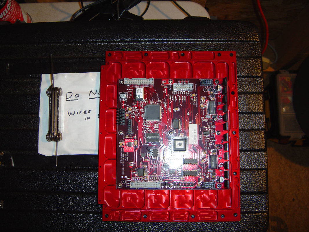
I'll keep this short and to the point. This is the old circuit board from the Paramount ME. If one follows the clearly written directions it is an easy matter to remove and properly replace the circuit board.
|
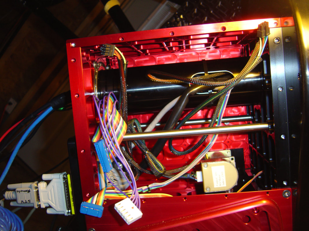
What struck me about this was how accessible the RA motor was, and how carefully the Paramount ME was wired. The other end of their "through the mount" wiring can be seen here.
|
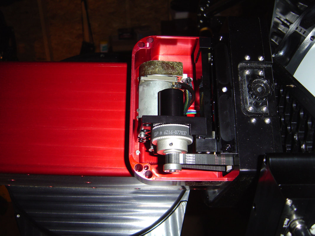
The declination panel has been removed, allowing the dec motor index angles to be recorded. These are later re-programmed into the mount using Paramount Me console in "The Sky". The engineering of this is a marvel to me. Again, it was easy to get into the declination compartment and the components were obviously meticulously designed, built and placed. Look carefully to the right with the image magnified (click on it) and you'll see an 8 legged visitor looking for a home in the Paramount ME !!! I didn't even see this guy until I was editing these images.
|
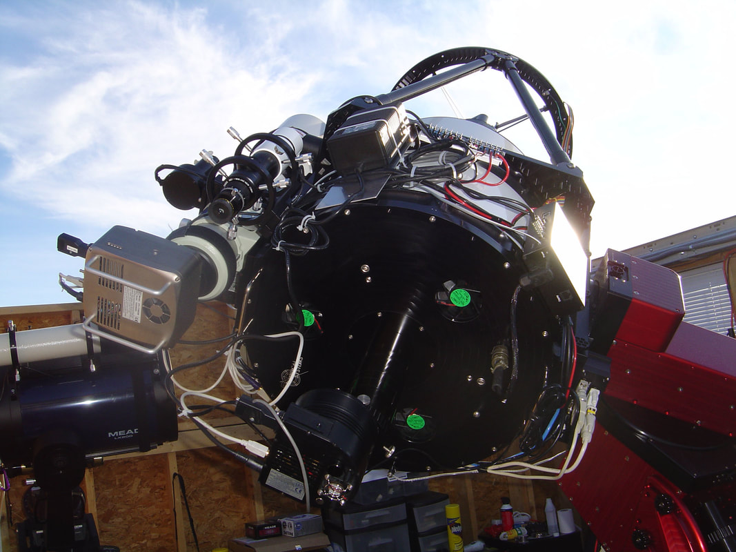
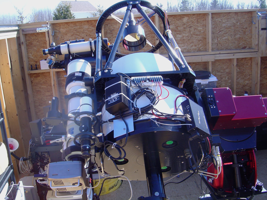
The observatory is now fully functional and is. in reality, more than I'd hoped. The RC-16/Paramount ME remains the work-horse for deep sky astro-imaging. With the APx.67 FLR the sampling is 0.57 arc-sec/pixel with a FOV of 14 x 20.8 arc-min (with the ST10-XME). Although slightly oversampling, this arrangement should be ideal for deep sky imaging, especially for faint galaxies (even at 2x2 binning the sampling is 1.14 arc-sec/pixel, and therefore still close to ideal for our New England Skys. I expect to be binning 1x1 for light and H-alpha images and 2x2 for RGB.
|

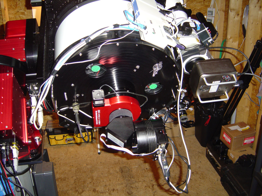
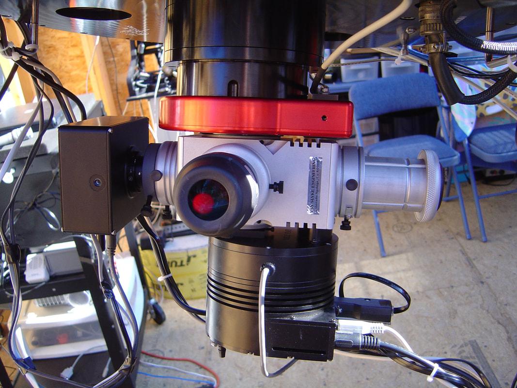
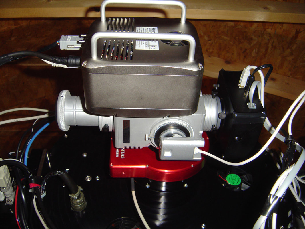
A great deal of equipment is packed onto this telescope. On the left the Icron ranger and Edgeport are nicely seen. The icron ranger essentially takes the USB signal from my remote Office Computer and converts it into a proprietary signal, which travels about 150 feet to the observatory. The Icron Ranger on the observatory end (the smaller white box to the left, also known as the REX Icron Ranger) then converts the signal back into a usable USB signal. The USB ports run to the cameras, the Paramount ME and one runs to the "Edgeport 4". This device converts the USB signal into a standard serial port signal (required for some of the devices, such as the RoboFocus and SBIG STV). Whats amazing is that with this set-up, NOT ONE cable is hanging from the telescope (they ALL run throughout the Paramount ME).
|
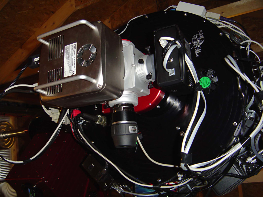
This view demonstrates that both the SBIG ST-10XME and the SBIG STL-11000 can be powered up and "ready to go" (without my having to go down to the observatory). With my set-up the ST10 runs using the "USB2" line (found under the "setting" tab in CCDSoft) and the STL-11000 uses the "USB" line (once selected either camera can be used). This allows me to use the Tak 106 FSQ for wide FOV imaging or the ST-10WME/RC-16 for higher resolution images. Also note that the power supply for the ST-10XME (which does not have an internal voltage regulator) has been wisely added to the telescope (you guessed it, courtesy of John Smith).
|
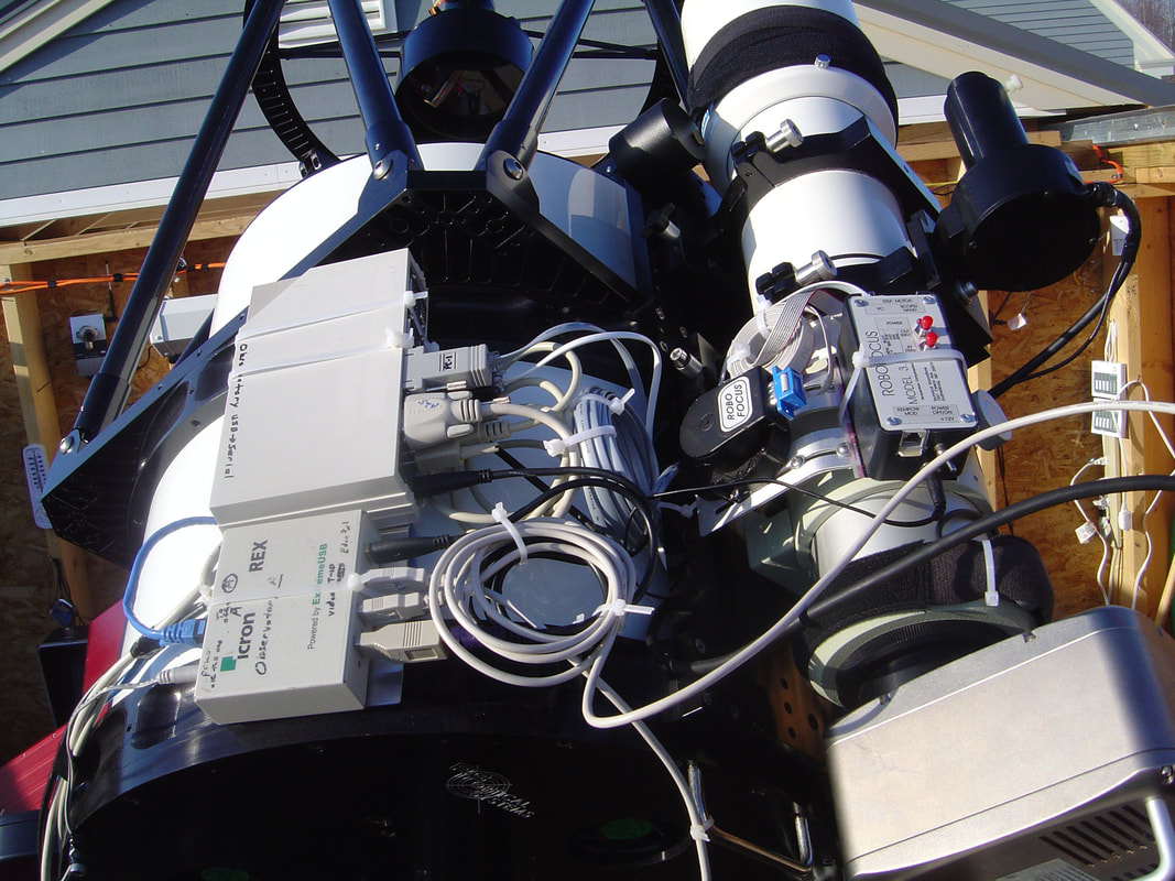
This gives you a better view of the Icron Ranger and Edgeport. As will be seen in the last image of this page the final arrangement uses a new (no writing on it) Icron Ranger and an Edgeport 4 (seen here is the Edgeport 8, which as more ports than is needed). Also visible is the RoboFocus used to focus the Tak 106 FSQ (FocusMax is the amazing freeware program which is used to focus both telescopes).
|
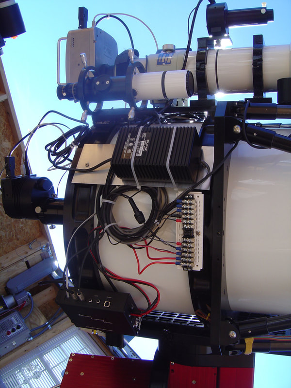
This view shows the opposite side of the RC-16, where the power supply for the ST-10XME can be seen. Also visable is a power strip for attaching the various powered items. The bottom 5 are Red (positive) and top 5 are Black (negative). There's a metal bridge that connects all the + together and a separate one to connect all the - wires (standard Radio Shack). After having an electrical fire I'm pretty sensitive about knowing what's what and what its' polarity should be (ie, use a digital voltmeter). Starting from the bottom the lines are as follow: 1) + Power input, 2) + to the TCC, 3) + to the STL-11000, 4) + to the St-10XME and 5) + to the RoboFocus). The 5 wires above are the mirror image Black (-) wires. The Icron Ranger receives its' power through the mount's "Auxillary 2" power line (uses 15 volts) and the Paramount ME's power goes directly to the mount from the AC power supply at the base of the telescope (via its AC to DC converter). The power supply to the RC-16 components is a simple Radio Shack 15 Amp converter.
|
Just another view of the last image. And yes, I also see the blurring on the left side of the image. There was a smudge on the lens of the camera. This wasn't noticed until after these images were loaded up, and I'm too lazy to re-shoot these images and re-load them (it's a lot of work !!!).
|

Of note, there is a laptop visible to the left. Although the observatory is completely robotic, there are times when I want to control telescope functions while working in the observatory. For example, while checking systems after the electrical fire ("use a voltmeter !!"). Using desktop remote this computer (which is hard wired via my LinkSys router to my office computer) to "control" the office computer. Although this initially seemed intimidating, it has a major advantage. I can control everything in the observatory WITHOUT plugging or unplugging a single wire (John Smith had to run this one by me several times before I realized how important this would be). Remember, everything is routed (hard wired) to my Office Computer, not the Observatory Computer. In a similar way the entire observatory can be run over the internet.
|
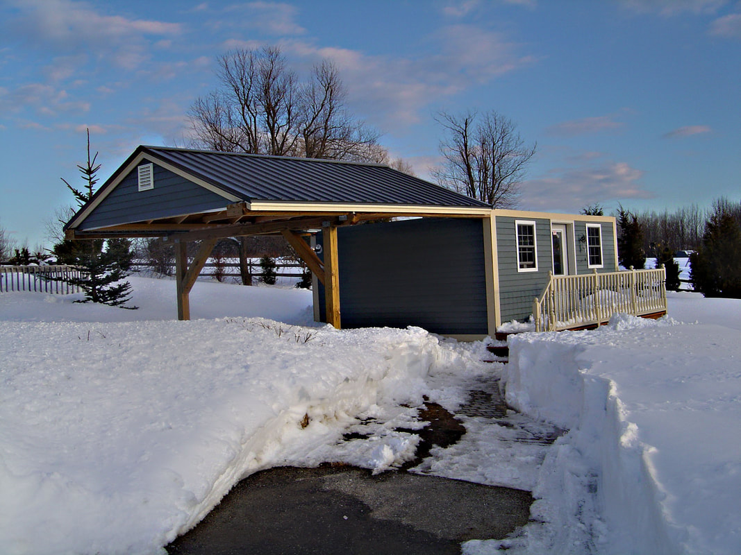
After returning from a week at Myrtle Beach I was greeted with 3-4 foot of snow and a layer of ice (blizzard followed by an ice storm in March of 2005). This image was taken after half of it had already melted, and a path was cut with a tractor-snowblower.
|
This image, as previously promiced, shows the equipment set-up as currently in place (April of 2005). The differences from the previous images are not obvious but are important. They include the following: 1) The first is the addition of the RCOS field flattener. The Ritchey-Chretien design is famous for being "coma free" (ie, nearly round stars even at the edges of the visual field). However the design does cause some degree of astigmatism, which is corrected my the field flattener. There is a great write-up on this by Russell Croman, which can be found on the RCOS website (currently at http://www.rcopticalsystems.com/fieldflattener.html).
2) The addition of an RCOS PIR (Precision Instrument Rotator). Without this centering guide stars is very difficult.
3) The addition of an SBIG AO-7 (which I believe will be very useful in our 'less than steady' New England skies (which often has the jet stream directly overhead).
4) The addition of an RCOS modified APx.67 FLR (which moves my image scale from 0.38 arc-sec/pixel to a more realistic .77 arc-sec/pixel). To optimize the distance of the FLR to the camera, RC Optical will modify AO-7 diagonal, as I had done (the rational for this is detailed on the RCOS website at ( http://www.rcopticalsystems.com/ap67xmod.html)
|
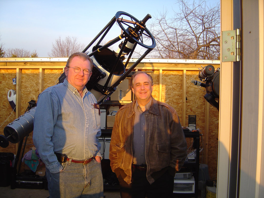
There's little I can add in terms of thanks to John Smith, as it's all been said elsewhere in this jungle of words (and yes, he's on the left...). He won't appreciate my thanking him in this website, but what the heck, he made the mistake of solving literally every problem I ran into (and so deserves to be thanked). Finding someone to consult with can be a bit intimidating, as you never know who or what you'll get. I was, to say the least, very fortunate. He spent many hours keeping me from making many of the mistakes I made in setting up my first observatory. I never ceased to be impressed by the breadth and depth of his knowledge, and his patience in sharing this. Without any exaggeration it was a privilege to have him consult on my project. As we worked together, I began to realize that besdies criss-crossing the country and taking on challenging projects (such as setting up observatories), he's written some great software (CCDAutopilot II is an increadibly useful program). Using his patience, adherence to basic principals such as the scientific method and a logical 'no frills' approach, he's improved upon many of the imaging systems I use (and many I haven't yet used). He is well respected and I hope will, some day, put his knowledge in book form (I'll tell you what John , we'll play an hand of Show Low, and if I win, you write the book and turn over Tucson, Arizona; if you win, I'll stop bugging you with my endless barrage of questions...I'll start the game....wow...I just pulled the 2 of clubs...OK, now it's your turn, good luck........).
|
While building my observatory I spent a good deal of time agonizing over 4 issues: 1) How can use the telescope visually without having to dismantle the CCD imaging set-up (potentially ruing my T-point model, not to mention the precision rotator, CCD camera, etc) 2) How can I, at the same time, add an OAG for imaging, 3) How can I do this with the necessary 2.7” of aperture (especially important if I eventually go to the 6303 camera or use my SBIG STL-11000) and 4) How can I do all the above with the limited back focus available.
To my surprise Van Slykes had already anticipated this issue and put together the Mega-Port Sidewinder. It does all the above and a good deal more. For details please look at his site at http://www.observatory.org/featside.htm . Rather than review this precision multi-port device (which he does in considerable detail), I’ll note a few import aspects from my perspective. The system is solid and flexure free. In my own testing, up to 20 minutes so far, my stars are perfectly round with the set-up shown above (using the OAG or SBIG internal guider). The OAG has the ability to rotate and can be adjusted by raising or lowering its’ position, though with the SBIG 402XME I appear to be seeing magnitude 14 stars (i.e., I seem to generally, though not always, have good guide stars without moving from the center of my target). The slider is nicely built and the mirror etched so that it will NEVER run into the OAG. Equally important to me is the fact that Paul (Van Slykes) took the time to walk me through the items I would need. And finally, being only 3” wide, I can use the system even with my limited back focus (more on this in the next image). Shortly after installing the Mega-Port Sidewinder I took my first look at Jupiter through the 16" RC Optical Ion Milled Optics. I’m still absorbing the details I could see, not just the bands, but the irregularities and bands within the major band pattern. This multi-port instrument was a great find and is already being appreciated by those who happen to “wander” on by the observatory.
|
This image is my ideal set-up, differeing from the previous image in that the camera being used is a SBIG STL-11000 (with a Class 1 SBIG 6303 arriving in 2 weeks !). This camera can be replaced with the SBIG STL-6303, without disrution the image train (the distance from the camera face plate adaptor to the CCD is the same for both cameras).
In setting up the image train on a RC telescope, the chip must be placed at the telescopes focal point (within 0.25"). If this isn't done, the coma free advantage of these hyperbolic mirrors is lost (the field flattener is added to reduce astigmatism). For my RC-16, this distance is 10.09" from the back of the telescopes faceplate. With this in mind the image train was set-up as follows: 1) RCOS flield flattener (2"), 2) RCOS Precision Rotator (2.55"), 3) AstroPhysics 2.7" Apeture Spacer (0.75"), 4) Van Slykes Mega-Port Sidewinder with adaptors (3.25"), and 5) STL-6303's "true" distance from the mounting adapter of the camera to the CCD, with filters in place (1.470"; obtained from mechanical drawings on SBIG website for STL series cameras). This places the CCD chip at 10.02" from the back of the RC-16 backplate. Since the true focal plane is 10.09" from the back of the telescopes base, the "error is 0.07". This is essentulally "dead on".
A good measurement to know is the distance from the mounting plate of the CCD camera to the chip, which for the STL series is 1.470" (this measurement takes the presence of a filter into account). One can then check the math by measuring the actual distance from the telescope's back plate to the STL's mounting adapter. In my case it was about 8.6 inches. This essentially matches the "expected distance" of 8.62" (10.09,ie, focal point, minus1.470, ie, adapter to chip distance on the STL series camera).
Now it's time to stop messing with the system and take some images with the STL-11000 or STL-6303 images. It will be possible, with this set-up (using Van Slykes Mega-Port Sidewinder), to use the internal SBIG imaging chip, the SBIG 402-XME autoguider OR to use the telescope visually WITHOUT changing the image train.
|
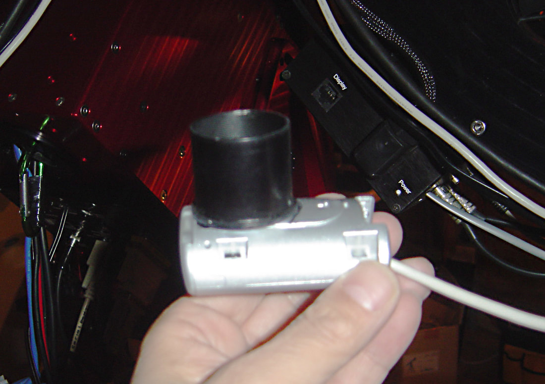
I couldn't resist diving back into planetary imaging. The RC-16 is ideal for planetary imaging with a FL of 3685 mm. Using the Philips to-U-Cam Pro 840, this put me at an image scale of .32 arc-sec/pixel and a FOV of 2.6 x 3.5 arc-min (Although we could debate this for hours, I determined there would be no real need for barlow or eyepiece projection. This is a real plus as any glass in the image train is bound to add noise). My biggest problem was getting the video chip at the focal point of the telescope (remember, RC scopes should have their primary/secondary mirror in their ideal position, ie, no focusing !!). The nosepiece I got with the webcam projected an extra 3/4 inch from a narrow neck located between the threads (into the web camera) and the 1.25" nosepiece. As can be seen, I cut this neck at its' base on the 1.25" nosepiece. To have a secure mounting surface I slightly widened the hole I created in the 1.25" nosepiece, allowing the neck to slide into it. This firm metal to metal contact was then super-glued (it's rock solid). I gained another .2" by removing the web cameras faceplate. To get the extra 0.5" I still needed I modified my Van Slykes MegaPort Sidewinder, as is illustrated in the next frame.
|
If you enlarge this image you'll see that I cut the viewport of the MegaPort sidewinder (where the web camera is attached), bringing the Philips To-U-Cam closer to the telescopes focal point (Paul Van Slykes is making me a proper one, but I just couldn't resist experimenting on my own !!). The 2" to 1.25" adapter is super-glued to the port, as there was no room for a thumbscrew (and I don't have anything to tap one with, even if there was room). This gave me enough working room to allow for an adjusting ring. This is important, as I can slip the camera out and insert an eyepiece for viewing. Once done, I can put the camera back and know it will be at its' ideal focus point. One note: I use my STV as a wide angle live viewfinder. Since the telescope is oriented to the STL-6303 in a fixed manner, I can use the STV to center objects on the web cam. This is a useful feature as the web cam and CCD camera do NOT look at the exact same point in the sky (the ability to center planets to the web camera in this way is critical if using the observtory remotely). I can do the same with my OAG (although I also used features in "The Sky" to build a reference point for the OAG). All's thats left for 100% robotic use of this web camera is a "robotic" way of pushing the MegaPort Mirror in (for planetary imaging) or out (for deep sky imaging). For now I'll have to actually walk out and move it by hand on those nights of planetary imaging (it'll be good exercise).
|